4402 N. Selland Ave, Fresno CA 93711 (559) 432-8873 FAX (559) 432-3059
www.m2inc.com Email: [email protected]
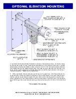
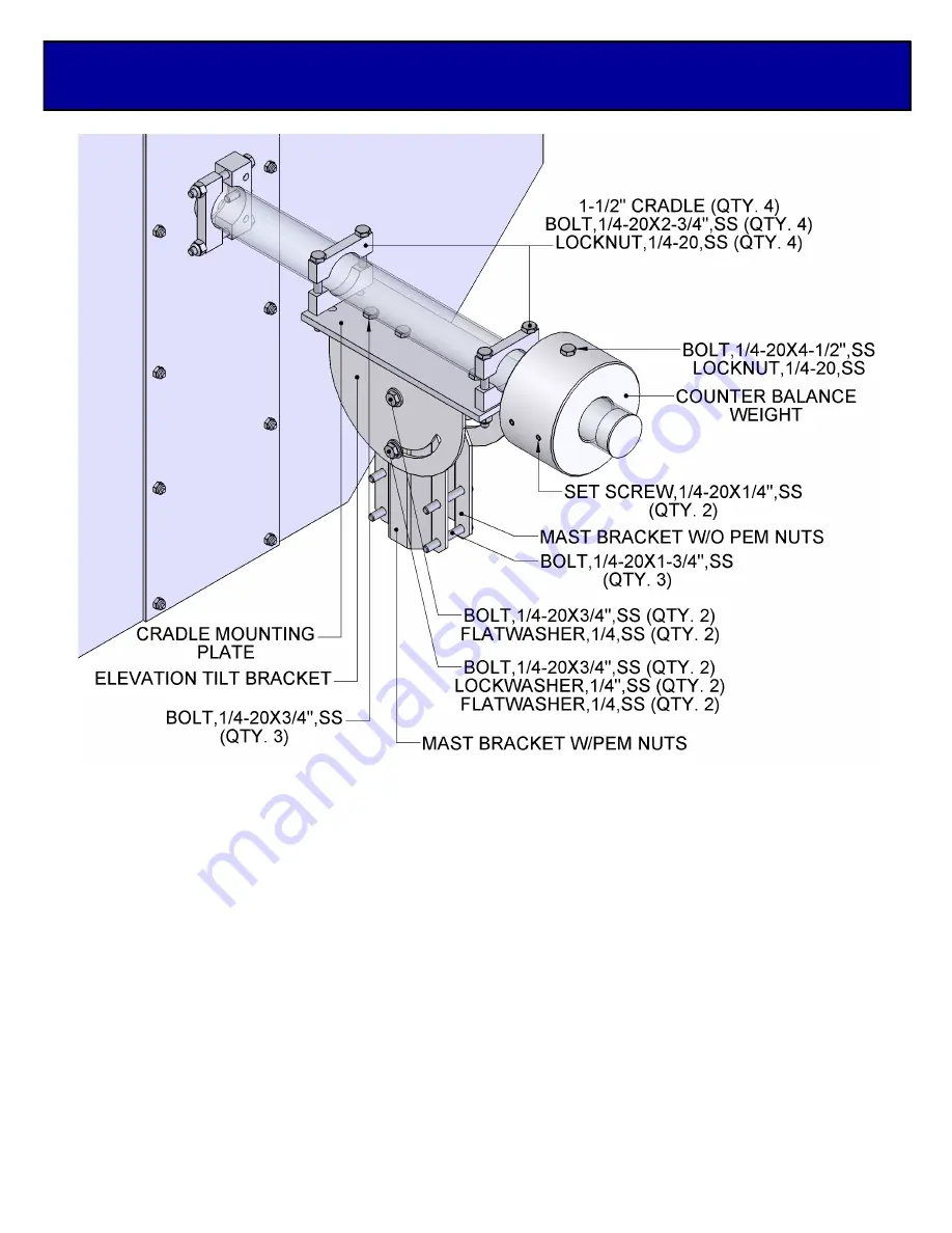
4. Assemble the Elevation Bracket hardware as shown on the assembly picture. For the time being
set the elevation angle to 0 deg. (mast bracket perpendicular to the antenna). Attach the 1.5” saddle
adapter plate to the elevation bracket. Next, using four 1/4-20 x 2 3/4” bolts and locknuts, attach the
four saddles loosely to the saddle adapter plate. Now slide the entire assembly onto the back of the
boom, position right up against the mounting plate collar, and set the feed connector to the desired
rotational orientation. Tighten the four saddle bolts.
5. With an associate, slide the antenna onto the top of a 2” support pole. Point the antenna to the
proper azimuth and elevation angles, and tighten all of 1/4-20 hardware on the mast clamp bracket.
Add the optional counter balance weight to the end of the heical, slide the weight to a position that
will provide balance to the antenna system, add 1/4-20 set screws to hold the position of counter bal-
ance. Drill through the counter balance locking pin hole and secure with a 1/4-20 x 4 1/2 bolt and lock
nut.
This completes the assembly.
OPTIONAL ELEVATION MOUNTING


