MDP-100T
5-2-55, Minamitsumori, Nishinari-ku, Osaka 557-0063 JAPAN
Phone: +81(6)6659-8201 Fax: +81(6)6659-8510 E-mail: [email protected]
EM-8226 Rev.1 P. 3 / 3
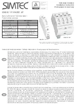
TERMINAL CONNECTION
Connect the unit as in the diagram below.
Be sure to cross-wire between the Ground terminal (G) and that of the protected equipment.
P1
P2
S1
S2
M-RESTER
Relay,
Coil, etc.
G
Discharge
Element
P1
P2
M-RESTER
G
Discharge
Element
1A
R
CONTROL ROOM
FIELD
The M-RESTER must be connected with its terminals S1 and S2 faced on power source side
in order that the fuses would be blown in case of shortcircuit of the discharge element.
1A
1A
1A
S1
S2
■
GROUNDING
M-RESTER
PROTECTED
EQUIPMENT
G
G
CROSSOVER WIRE
GROUNDING
(100 ohms or less)
A crossover wire between M-RESTER ground and the ground or
metallic housing of the equipment is required for protection.
If the protected equipment has no ground terminal, ground the
M-RESTER only.
When the M-RESTER is mounted with DIN Rail Mounting Adapter,
connect the grounding wire to the mounting screw of the M-RESTER.
WIRING INSTRUCTIONS
■
SCREW TERMINAL
Torque: 0.8 N·m
MAINTENANCE
Check surge protectors periodically. Many cases of light-
ning are ignored, and even lightning at a far distance often
causes inductive surges.
We recommend that you check your surge protector about
twice a year, before and after the rainy season. Check
whenever you experience a strong lightning occurrence.
Checking procedure is explained in the following:
■
CHECKING
WIRING
1) Make sure that wiring is done as instructed in the con-
nection diagram.
2) Make sure that the Ground terminal (G) is connected to
the metallic housing of protected equipment.
3) Make sure that the Ground terminal (G) is grounded to
earth.
DISCHARGE FUNCTION
The M-RESTER Tester is available for checking the ele-
ment module of this surge protector.
If you do not have one, approximate checking can be con-
ducted as following.
1) Remove all wiring connected to the surge protector when
you test the element module.
2) Check resistance across the following terminals on the
high resistance range of multimeter and confirm no con-
duction. The meter shows the same value as it will show
when these terminals are open.
Terminals (S1) – (S2), (P1) – (P2)
3) Check that discharging occurs across the following ter-
minals with a 500V DC 1000 MΩ insulation tester (The
tester shows ≤ 20MΩ).
Terminals (S1) – (S2), (S1) – (G), (S2) – (G)
If any of the above tests shows negative, replace the protec-
tor.