


M1EXS-2
5-2-55, Minamitsumori, Nishinari-ku, Osaka 557-0063 JAPAN
Phone: +81(6)6659-8201 Fax: +81(6)6659-8510 E-mail: [email protected]
EM-5986-A Rev.1 P. 4 / 5
EXTERNAL VIEWS
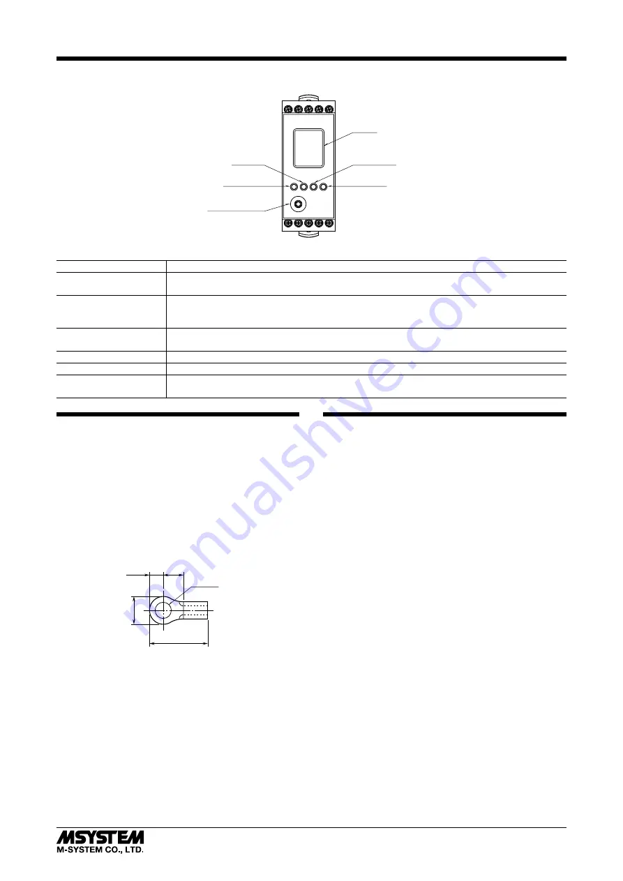
Mode Button
Set Button
Display
Configurator Jack
Up Button
Down Button
COMPONENT
FUNCTION
Display
Indicates present values, setting values and abnormal information. Two types of present values at up-
per and lower are displayed by setting.
Mode button
Used to shift from measuring mode to each setting mode. Destination to shift is changed by the time
pressing and holding the button. Used to return from each setting mode to measuring mode (press and
hold for 2 sec. or more).
Set button
Used to change setting value of setting parameter. When at setting changeable state, used to enter
(save) the setting value. Used to move on through digits of setting value at setting changeable state.
Up button
Used to shift through setting parameter, and to increase or select setting value.
Down button
Used to shift through setting parameter, and to decrease or select setting value.
Configurator Jack
Used to configure with M1E configurator software (model: M1ECFG). At the same time, set the lockout
setting of the unit to ‘lock’.
WIRING INSTRUCTIONS FOR BASE
■
SCREW TERMINAL
Torque: 0.5 N·m
■
SOLDERLESS TERMINAL
Refer to the drawing below for recommended ring tongue
terminal size. Spade tongue type is also applicable.
Recommended manufacturer: Japan Solderless Terminal
MFG.Co.Ltd, Nichifu Co.,ltd (Solderless terminals with in-
sulation sleeve do not fit)
Applicable wire size: 0.25 to 1.65 mm
2
12max
6max
3max
4min
3.2 dia.
(mm)
CHECKING
1) Terminal wiring: Check that all cables are correctly con-
nected according to the connection diagram.
2) Power input voltage: Check voltage across the terminal
19 – 20 with a multimeter.
3) Input signal and power input voltage: Check wiring
across M1EXS-2 and self-synch as shown in connection
diagram. The power input of the unit has polarity. Be
sure that the connection for R1 and R2 of the self-synch.
4) Output: Check that the load resistance meets the de-
scribed specifications.


