71VR1
5-2-55, Minamitsumori, Nishinari-ku, Osaka 557-0063 JAPAN
Phone: +81(6)6659-8201 Fax: +81(6)6659-8510 E-mail: [email protected]
EM-7403-A Rev.7
P. 6 / 8
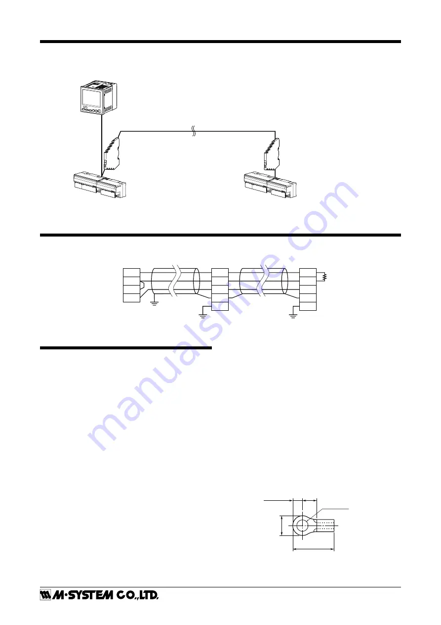
SYSTEM CONFIGURATION EXAMPLES
MODBUS WIRING DIAGRAM
RS-485
DA
DB
DG
SLD
FG
R7M
RS-485
DA
DB
DG
SLD
FG
R7M
71VR1
T1
T2
T3
T4
*
1. Use a terminating resistor when the device is at the extreme end of a transmission line.
Terminator
*
1
RS-485 (Modbus-RTU)
・・・・・・・・・・・・・・・・・・・・
*
1. Insert lightning surge protectors recommended in this example if necessary.
Paperless Recorder (model: 71VR1)
Modbus I/O Module (model: R7M)
Modbus I/O Module (model: R7M)
Lightning Surge Protector for RS-485/422
(model: MD74R or MDP-4R)
*
1
Lightning Surge Protector for RS-485/422
(model: MD74R or MDP-4R)
*
1
PREPARATION & WIRING TO THE UNIT
■
MEMORY CARD
• How to insert a memory card
1) Initialize a memory card
2) Make sure the Lock switch is slid up (unlock position) so
that the memory card is writable.
3) Insert the memory card into the memory card slot com-
pletely.
4) CARD in the sub display turns to green.
• How to remove a memory card
1) When the unit is recording, press STOP RECORDING
button in the CONTROL MENU to stop recording.
2) Press the REMOVE MEMORY CARD button in the
CONTROL MENU.
3) Push the memory card to remove it.
■
WIRING
• Power supply
Confirm the power input rating marked on the product.
1) Remove the terminal cover.
2) Loosen three screws on the power supply terminals.
3) Connect the power cables and the earth cable to the pow-
er supply terminals.
4) Replace the terminal cover.
• Input/Output
Follow the procedure shown below when a DC signal is con-
nected to DC Input Ai 1. For other input/output connec-
tions, similar procedure should be followed.
1) Turn the power off.
2) Remove the terminal cover.
3) Connect the (+) side of a signal source to V (21), connect
the (–) side to COM (23).
4) Replace the terminal cover.
Please choose appropriate solderless terminals for the in-
put/output terminals and the power terminals, referring to
the figure shown below. Appropriate tightening torque is
0.5 N·m.
Input terminal block: M3 screw terminal connection
Screw terminal material: Nickel plated steel
Appropriate wire size: 0.3 to 0.75 mm
2
3.2 (.13) dia.
4 min.
(.16)
12 (.47) max.
6 max
.
(.24)
3 (.12) max.


