IO-390-D Series Engine Maintenance Manual
© 2020 Avco Corporation. All Rights Reserved
72-20
March 2020
Page 173
IO-390-D Series Engine Maintenance Manual
(6)
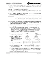
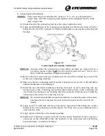
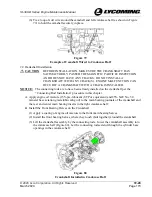
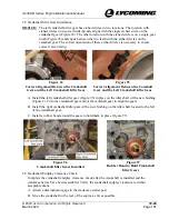
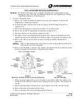
Tie a loop of soft wire around the camshaft and left crankcase half (as shown in Figure
79) to hold the camshaft securely in place.
Figure 79
Example of Camshaft Wired to Crankcase Half
22.
Crankshaft Installation
CAUTION
BEFORE INSTALLATION, MAKE SURE THE CRANKSHAFT HAS
SATISFACTORILY PASSED THE MAGNETIC PARTICLE INSPECTION
AND DOES NOT HAVE ANY CRACKS. DO NOT INSTALL A
CRANKSHAFT WITH ANY CRACK(S). ENGINE MALFUNCTION CAN
OCCUR IF A CRANKSHAFT WITH A CRACK IS INSTALLED.
NOTICE:
The connecting rods are to have been already installed on the crankshaft per the
“Connecting Rod Installation” procedure in this chapter.
A.
Apply engine oil mixture (15% pre-lubricant (STP or equivalent) and 85% SAE No. 50
mineral base aviation grade lubricating oil) to the main bearing journals of the crankshaft and
the rear and center main bearing inserts in the right crankcase half.
B.
Install the Front Bearing Halves on the Crankshaft
(1)
Apply a coating of engine oil mixture to the front main bearing halves.
(2)
Install the front bearing halves, where they touch (butt together) around the crankshaft.
(3)
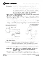
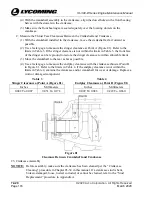
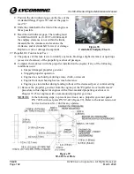
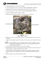
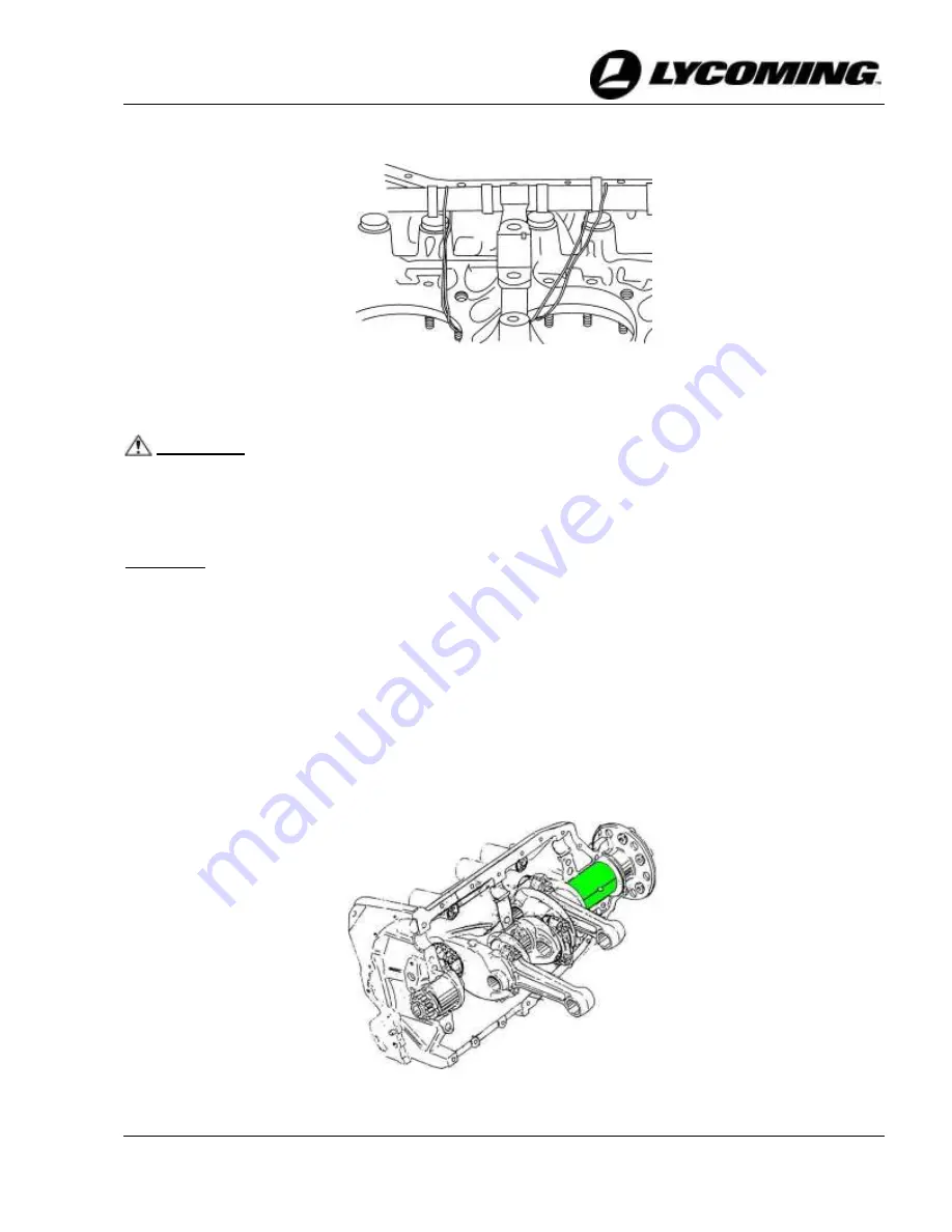
Lift the crankshaft assembly by the connecting rods. Lower the crankshaft assembly into
the crankcase half (Figure 80). Let the connecting rods extend through the cylinder base
openings in the crankcase half.
Figure 80
Crankshaft Installed in Crankcase Half

