IO-390-D Series Engine Maintenance Manual
72-20
© 2020 Avco Corporation. All Rights Reserved
Page 164
March 2020
IO-390-D Series Engine Maintenance Manual
CAUTION
CORRECT INSTALLATION OF THE NEW NUT ON EACH NEW
CONNECTING ROD BOLT IS NECESSARY FOR CORRECT
CONNECTING ROD ASSEMBLY. EACH CONNECTING ROD NUT
HAS TWO DIFFERENT SURFACES, ONCE SURFACE IS FLAT AND
THE OTHER IS CHAMFERED AND HAS A RAISED LIP. BE SURE
TO INSTALL EACH NUT ON THE CONNECTING ROD BOLT WITH
THE FLAT FACE TOUCHING THE ROD. THE CHAMFERED
RAISED LIP SURFACE IS AWAY FROM THE ROD.
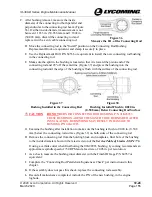
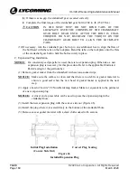
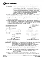
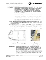
(9)
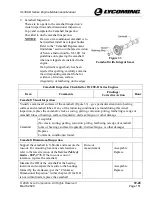
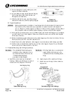
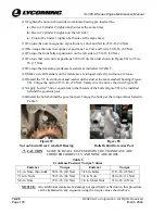
Install a new nut on each new connecting rod bolt where the flat face of the nut touches
the connecting rod as shown in Figure 51.
(10)
Torque the connecting rod bolts per the torque values in the latest revision of Service
Instruction No. SI-1458. (Stretch bolts require an initial torque and are then torqued to
the correct stretched length.)
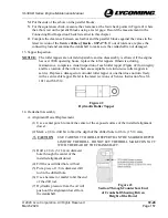
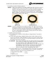
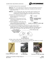
(11)
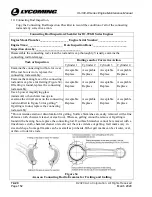
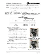
Measure the side clearance between the connecting rod and crankshaft with a feeler gage
where shown in Figure 52. The clearance is to be 0.004 to 0.016 in. (0.102 to 0.406 mm)
(service or overhauled) and 0.004 to 0.010 in. (0.102 to 0.254 mm) (on rebuilt engines).
Compare the results to the measurements previously recorded.
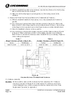
Figure 51
Connecting Rod Nut Installation
Figure 52
Connecting Rod Side Clearance
F.
Counterweight Installation
CAUTION
DURING INSTALLATION, DO NOT MAKE SCORES, SCRATCHES, OR
ETCH MARKINGS OF ANY KIND ON THE CRANKSHAFT,
COUNTERWEIGHTS AND ROLLERS. A MARK IN ANY OF THESE
AREAS CAN CAUSE THE PART TO WEAKEN AND TO FAIL.
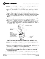
(1)
Make sure the counterweights of the correct order and part number are to be installed on
the crankshaft. Refer to the latest revision of Service Instruction No. SI-1012.
CAUTION
DO NOT INSTALL TWO DIFFERENT ROLLERS ON THE SAME
COUNTERWEIGHT. ALL MUST BE MATCHED PAIRS OF
IDENTICAL PARTS.
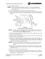
(2)
Measure the outside diameter of each roller to be installed to make sure it is in
compliance with the dimensions in the latest revision of Service Instruction No. SI-1535.


