IO-390-D Series Engine Maintenance Manual
© 2020 Avco Corporation. All Rights Reserved
72-20
March 2020
Page 157
IO-390-D Series Engine Maintenance Manual
M.
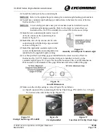
Put the ends of the arbors on the parallel blocks.
N.
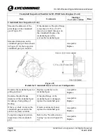
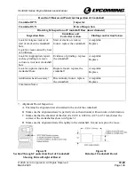
For the squareness check, measure the clearance at the four check points in Figure 41 where
the arbors rest on the parallel blocks using a feeler gage. Record the measurement in the
Connecting Rod Inspection Checklist earlier in this chapter
O.
Compare the clearance between each arbor and the parallel blocks against the values in the
latest revision of the
Service Table of Limits - SSP-1776
. If out of tolerance, replace the
connecting rod and examine the crankshaft to make sure the crankshaft is not damaged.
13.
Tappet Inspection
NOTICE:
The roller tappets are not field repairable and no disassembly is allowed. If the engine
has over 2000 operating hours, replace the roller tappets. Otherwise, during
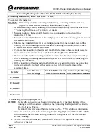
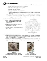
maintenance, complete a visual inspection of each roller tappet (Figure 42) for integrity
and free rotation of the roller which are acceptable to return in-use roller tappets to
service. Replace a damaged or corroded roller tappet or one that does not turn freely
with a serviceable tappet. Refer to the latest revisions of Service Instruction Nos. SI-
1011 and SI-1514.
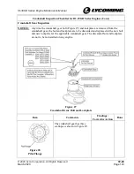
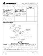
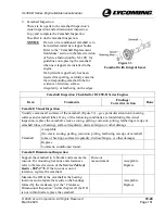
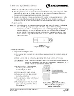
Figure 42
Hydraulic Roller Tappet
14.
Crankshaft Assembly
A.
Alignment Dowel Replacement
(1)
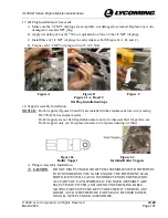
Use a center punch to mark the center of the exposed surface of the installed alignment
dowel.
(2)
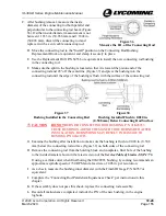
Mark a 1/8 in. drill bit to limit the depth of the drilled hole to 0.6 in. (15.14 mm).
CAUTION
USE CARE NOT TO DRILL DEEPER THAN THE MARKED DEPTH
LIMIT OF THE DRILL. DO NOT LET THE DRILL MAKE CONTACT
WITH THE REAR OF THE CRANKSHAFT.
(3)
Drill a 1/8 in. (3.18 mm) diameter
hole through the center of the
installed alignment dowel.
(4)
Fill the new drilled hole with oil.
(5)
Put a piece of 1/8 in. diameter drill
rod in the drilled hole.
(6)
Use a hammer or mallet to hit the end
of the drill rod.
(7)
Hydraulic pressure from the oil will
push out the alignment dowel from
the crankshaft.
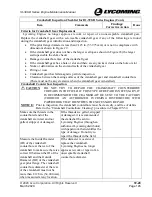
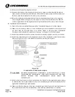
Figure 43
Section Through Counterbore End
of Crankshaft Showing Driven
Height of the Dowel

