background image

Содержание 0-360

Страница 1: ... pages in the operator s manual PREVIOUS REVISIONS July 1989 3 5 March 1990 1 5 1 6 2 9 2 10 2 11 2 12 2 13 Added page 3 18A 3 29 5 4 May 1996 1 5 l 6 l 7 2 2 Added page 2 2A B 2 9 2 10 2 11 2 12 2 13 2 14 3 12 Added page 3 12A B 3 14 Added page 3 14A B 3 15 3 16 Added pages 3 16A 3 16B 3 17 3 l 3 26 Added pages 3 26A B 3 4OAJB 3 50 Added pages 3 5OA 3 50B 3 51 CURRENT REVISIONS April 1998 3 3 3 4...

Страница 2: ...NT REVISIONS July 1989 December 1999 3 5 1 7 2 2A Adds page 2 2B 2 10 March 1990 2 13 3 12 3 15 3 23 3 40A 1 5 1 6 2 9 2 10 2 11 2 12 Adds page 3 40B 8 1 2 13 Added page 3 18A 3 29 5 4 May 1996 1 5 1 6 1 7 2 2 Added page 2 2A B 2 9 2 10 2 11 2 12 2 13 2 14 3 12 Added page 3 12A B 3 14 Added page 3 14A B 3 15 3 16 Added pages 3 16A 3 16B 3 17 3 18 3 26 Added pages 3 26A B 3 40A B 3 50 Added pages 3...

Страница 3: ...ferenced in this publication are trademarks or registered trademarks of their respective companies For additional information Mailing address Textron Lycoming 652 Oliver Street Williamsport PA 17701 U S A Phone Factory 570 323 6181 Sales Department 570 327 7268 Fax 570 327 7101 Textron Lycoming s regular business hours are Monday through Friday from 8 00 AM through 5 00 PM Eastern Time 5 GMT Visit...

Страница 4: ...UBLICATION NO DATE 60297 12 April1989 add to or delete current pages in CURRENT REVISIONS May 2000 3 12A Adds page 3 12B 3 13 May 1996 1 5 1 6 1 7 2 2 Added page 2 2A B 2 9 2 10 2 11 2 12 2 13 2 14 3 12 Added page 3 12A B 3 14 Added page 3 14A B 3 15 3 16 Added pages 3 16A 3 16B 3 17 3 18 3 26 Added pages 3 26A B 3 40A B 3 50 Added pages 3 50A 3 50B 3 51 April 1998 3 3 3 4 Addedpage 3 4A B Decembe...

Страница 5: ...referenced in this publication are trademarks or registered trademarks of their respective companies For additional information Mailing address Textron Lycoming 652 Oliver Street Williamsport PA 17701U S A Phone Factory 570 323 6181 Sales Department 570 327 7268 Fax 570 327 7101 Textron Lycoming s regular business hours are Monday through Friday from 8 00 AM through 5 00 PM Eastern Time 5 GMT Visi...

Страница 6: ...OPERATOR S MANUAL Lycoming 0 360 HO 360 10 360 AIO 360 HIO 360 TIO 360 SERIES AIRCRAFT ENGINES 6thEdition September 1999 Approvedby F A A PartNo 60297 12 Printed inU S A ...

Страница 7: ...procedures can result in poor engine performance and power loss Also if power and speed limitations specified in this manual are exceeded for any reason damage to the engine and personal injury can happen Consult your local FAA approved maintenance facility SERVICEBULLETINS INSTRUCTIONS ANDLETTERS Although the information contained in this manual isup to date at time of publication users are urged...

Страница 8: ... con tain various Warnings and Cautions which must be carefully read in order to minimize the risk of personal injury or the use of improper ser vice methods that may damage the engine or render it unsafe It is also important to understand that these Warnings and Cautions are not all inclusive Textron Lycoming could not possibly know evaluate or advise the service trade of all conceivable ways in ...

Страница 9: ...WARRANTY LIMITED NEWANDREMANUFACTURED RECIPROCATING AIRCRAFT ENGINE WHATTEXTRON LYCOMING PROMISESYOU ...

Страница 10: ...THISLIMITED WARRANTYIS EXCLUSIVEAND INLIEU OF ALL OTHER WARRANTIES AND REPRESEN ...

Страница 11: ...nanceexpensesor consumableitems Theobligationson the partof Textron Lycoming set forthaboveare your exclusiveremedyand the exclusiveliabilityof Textron Lycoming This warrantyallocates therisk of productfailure betweenyou and Textron Lycoming as permittedby applicable law Textron Lycoming reservesthe rightto denyany warrantyclaimif it reasonablydeterminesthat theengine or part has been subject to a...

Страница 12: ...AMAGES INCLUDING BUTNOT LIMITED TO LOSSOF PROFITSOR REVENUES LOSS OF USE OFTHE ENGINEORCOSTOF A REPLACEMENT No agreement varying this warranty or Texton Lycoming s obligations under it will be binding upon Texron Lycomingunless in writing signed by a duly authorized repesentative of TextronLycoming Effective October 1 1995 Revision J Textron Lycoming Williamsport Pennsylvania ...

Страница 13: ......

Страница 14: ......

Страница 15: ...e SECTION 1 DESCRIPTION 1 1 SECTION 2 SPECIFICATIONS 2 1 SECTION 3 OPERATING INSTRUCTIONS 3 1 SECTION 4 PERIODIC INSPECTIONS 4 1 SECTION 5 MAINTENANCE PROCEDURES 5 1 SECTION 6 TROUBLE SHOOTING 6 1 SECTION 7 INSTALLATION AND STORAGE 7 1 SECTION 8 TABLES 8 1 ...

Страница 16: ...Figure 1 3 4 Right Side View IO 360 A1A ...

Страница 17: ...Figure 2 3 4 Left Rear View TIO 360 AlB ...

Страница 18: ...s ValveOperating Crankcase Crankshaft ConnectingRods Pistons AccessoryHousing Oil Sump CoolingSystem Induction Systen Lubrication System PrimingSystem Ignition System Mechanism ng m em 1 1 1 1 1 1 1 1 1 2 1 2 1 2 1 2 1 2 1 2 1 2 1 4 1 4 1 4 ModelApplication Table 1 5 ...

Страница 19: ...of the basic model Example model 10 360 C has clockwise rotation of the crankshaft Therefore LIO 360 C has counter clockwise rotation of the crankshaft Likewise the rotation of the accessory drives of the LIO 360 C are opposite those of the basic model as listed in Section 2 of this manual The letter D used as the 4th or 5th character in the model suffix denotes that the particular model employs d...

Страница 20: ...nkshaft ends and bronze bushings in the piston ends The bearing caps on the crankshaft ends are retained by two bolts and nuts through each cap Pistons The pistons are machined from an aluminum alloy The piston pin is of a full floating type with a plug located in each end of the pin Depending on the cylinder assembly pistons may be machined for either three or four rings and may employ either hal...

Страница 21: ...odel 10 360 B1A which is equipped with a Simmonds type 530 fuel injector See Table 1 for model application The fuel injection system schedules fuel flow in proportion to air flow and fuel vaporization takes place at the intake ports A turbocharger is mounted as an integral part of the TIO 360 series engines Automatic waste gate control of the turbocharger provides constant air density to the fuel ...

Страница 22: ...rol position Complete flexibility of operation is provided by the manual mixture control which permits the adjustment of the amount of injected fuel to suit all operating conditions Moving the mixture control to Idle Cut Off results in a complete cut off of fuel to the engine Lubrication System All models except AIO 360 series The full pressure wet sump lubrication system is actuated by an impelle...

Страница 23: ... 20 S4LN 200 S4LN 204 S4LN 200 S4LN 204 S4LN 1227 S4LN 1209 Carburetor MA 4 5 PSH 5BD MA 4 5 MA 4 5 HA 6 HA 6 HA 6 MA 4 5 HA 6 MA 4 5 MA 4 5 S4LN 1227 S4LN 21 4273 4373 4371 4371 4251 S4LN 1209 S4LN 204 4270 4370 4370 4370 4251 S4LN 21 S4LN 20 MA 4 5 S4LN 200 4051 S4LN 21 S4LN 21 S4LN 200 4191 S4LN 204 4050 S4LN 20 S4LN 20 S4LN 204 4191 MA 4 5 MA 4 5 PSH 5BD MA 4 5 MA 4 5 HA 6 MA 4 5 D4LN 3021 Mod...

Страница 24: ...S4LN 200 S4LN 200 S4LN 200 4347 S4LN 204 S4LN 204 S4LN 200 4370 S4LN 200 S4LN 200 S4LN 200 S4LN 204 S4LN 1208 S4LN 1209 S4LN 1208 S4LN 1208 D4LN 3021 D4LN 3200 MA 4 5AA PSH 5BD PSH 5BD HA 6 Fuel Injector RSA 5AB1 RSA 5AD1 RSA 5AD1 RSA 7AA1 RSA 5AB1 RSA 5AB1 S4LN 200 S4LN 1227 S4LN 1208 S4LN 1227 4372 S4LN 200 S4LN 200 S4LN 204 S4LN 1209 S4LN 1209 S4LN 1209 4370 S4LN 204 S4LN 204 RSA 5AD1 RSA 5AD1 ...

Страница 25: ...D D4LN 3000 RSA 5AD1 AIO 360 AIA A2A S4LN 1208 S4LN 1209 RSA 5ADI AIB A2B B1B S4LN 1227 S4LN 1209 RSA 5AD1 TIO 360 A1A A1B A3B6 S4LN 1208 S4LN 1209 RSA 5ADI C1A6D D4LN 3021 Models with counterclockwise rotation employ S4RN series See latest edition of Service Instruction No 1443 for alternate magnetos Engine models with letter D as 4 or 5 character in suffix denotes dual magnetos in single housing...

Страница 26: ...SPECIFICATIONS Specifications O 360 A B C D F 2 1 HO 360 A B 2 2 IO 360 A B C D E F J K 2 3 AIO 360 A B 2 4 HIO 360 A B 2 4 HIO 360 C D 2 5 HIO 360 E F 2 6 TIO 360 A C 2 7 Accessory Drives 2 8 Detail Weights Engines 2 9 Dimensions 2 10 ...

Страница 27: ...o Propellerdriverotation viewedfrom rear 286 180 2700 5 125 4 375 361 0 8 5 1 1 3 24 25 028 080 1 1 Clockwlse 0 360 C2Donly Take offrating 180 HP 2900 RPMand 28 in hg SPECIFICATIONS 0 360 B DSERIES FAAType Certificate Rated horsepower Rated speed RPM Bore inches Stroke inches Displacement cubic inches Compressionratio Firing order Spark occurs degreesBTC Valverockerclearance hydraulic tappets coll...

Страница 28: ...lverockerclearance hydraulictappetscollapsed 028 080 Propellerdriveratio 1 1 Propeller driverotation viewedfromrear Clockwise SPECIFICATIONS HO 360 A C FAATypeCertificate 286 Ratedhorsepower 180 Ratedspeed RPM 2700 Bore inches 5 125 Stroke inches 4 375 Displacement cubicinches 361 0 Compression ratio 8 5 1 Firingorder 1 3 2 4 Spark occurs degrees BTC 25 Valverockerclearance hydraulic tappets colla...

Страница 29: ...collapsed 028 080 Propeller drive ratio 1 1 Propeller drive rotation viewed from rear Clockwise SPECIFICATIONS 10 360 L2A FAA Type Certificate 1E10 Rated horsepower 160 Rated speed RPM 2400 Bore inches 5 125 Stroke inches 4 375 Displacement cubic inches 361 0 Compression ratio 8 5 1 Firing order 1 3 2 4 Spark occurs degrees BTC 25 Valve rocker clearance hydraulic tappets collapsed 028 080 Propelle...

Страница 30: ...c tappets collapsed 028 080 Propeller drive ratio 1 1 Propeller drive rotation viewed from rear Clockwise This engine has an alternate rating of 160 HP at 2400 RPM 10 360 CIG6 FAA Type Certificate IEIO Rated horsepower 200 Rated speed RPM 2700 Bore inches 5 125 Stroke inches 4 375 Displacement cubic inches 361 0 Compression ratio 8 7 1 Firing order 1 3 2 4 Spark occurs degrees BTC 20 Valve rocker ...

Страница 31: ...e inches 5 125 Stroke inches 4 375 Displacement cubic inches 361 0 Compression ratio 8 5 1 Firing order 1 3 2 4 Spark occurs degrees BTC 25 Valverocker clearance hydraulic tappets collapsed 028 080 Propeller drive ratio 1 1 Propeller drive rotation viewed from rear Clockwise 10 360 B1Conly Rated 177HP NOTE On the following modelengines the magneto spark occursat 20 BTC Con sult nameplatebefore tim...

Страница 32: ...2700 5 125 4 375 361 0 8 7 1 1 3 2 4 25 028 080 1 1 Clockwise FAA Type Certificate Rated horsepower Rated speed RPM Bore inches Stroke inches Displacement cubic inches Compression ratio A series Compression ratio B Series Firing order Spark occurs degrees BTC Valve rocker clearance hydraulic tappets collapsed Propeller drive ratio Propeller drive rotation viewed from rear 1E10 180 2900 5 125 4 375...

Страница 33: ...028 080 Propeller drive ratio 1 1 Propeller drive rotation viewed from rear Clockwise SPECIFICATIONS HIO 360 D SERIES FAA Type Certificate 1E10 Rated horsepower 190 Rated speed RPM 3200 Bore inches 5 125 Stroke inches 4 375 Displacement cubic inches 361 0 Compression ratio 10 0 1 Firing order 1 3 2 4 Spark occurs degrees BTC 20 Valve rocker clearance hydraulic tappets collapsed 028 080 Propeller d...

Страница 34: ...ler Drive Ratio 1 1 Propeller Drive Rotation viewedfrom rear Clockwise HIO 360 E has a rating of 205 HP at 2900 RPM and 36 5 in Hg manifold pressure when equipped with turbocharger kit SK 28 121000 or equivalent HIO 360 F1AD SERIES FAA Type Certificate 1E10 Rated Horsepower 190 Rated Speed RPM 3050 Bore Inches 5 125 Stroke Inches 4 375 Displacement Cubic Inches 361 0 Compression Ratio 8 0 1 Firing...

Страница 35: ...BTC 20 ValveRocker Clearance hydraulictappets collapsed 028 080 Propeller Drive Ratio 1 1 Propeller Drive Rotation viewed from rear Clockwise TIO 360 C SERIES FAA Type Certificate E16EA Rated Horsepower 210 Rated Speed RPM 2575 Bore Inches 5 125 Stroke Inches 4 375 Displacement Cubic Inches 361 0 Compression Ratio 7 3 1 Firing Order 1 3 2 4 Spark occurs Degrees BTC 20 ValveRocker Clearance hydraul...

Страница 36: ...m Hyd pump Vacuum Prop Gov 16 556 1 1 910 1 2 500 1 3 20 1 0 500 1 1 000 1 1 300 1 0 866 1 0 895 1 0 866 1 1 000 1 0 500 1 1 300 1 1 300 1 Counter Clockwise Clockwise Clockwise Clockwise Clockwise Clockwise Counter Clockwise Clockwise Clockwise Counter Clockwise Counter Clockwise Counter Clockwise Counter Clockwise NOTE Engines with letter L in prefix will have oppositerotation to the above When a...

Страница 37: ...tor or alternator withmounting brack et Turbocharged models include turbocharger mounting bracket ex haust manifold controls oil lines and baffles Model Lbs 0 360 Series C4P 275 D2A 282 B2A B2C 284 C1E C2E 285 AlAD A3AD C1F C2D 288 A1C AlD A2D A3D C2B C2C J2A 289 AlA A2A A3A ALD ClA C2A 290 A2F 291 AlP ClG 292 A1G A2G 293 A1H 294 A4M A4P A1F6D C4F 295 A4K A4N A5AD 296 A4D AG6D 297 A4A A1F6 A1H6 29...

Страница 38: ...A BIB CIA 288 10 360 Series L2A 278 BIC 289 BIA 295 BIE 296 BID 297 BIB 299 M IA 300 BIF B2F 301 BIG6 305 B4A 307 B2F6 308 K2A 311 AID6D A3D6D C IA 319 CIB 320 CIC DIA 322 JIAD 323 AI A A2A CIF CIG6 324 AIC A2C AID 325 AIB A2B 326 CID6 328 CIC6 329 IB 6D A3B6D JIA6D 330 AIB6 A3B6 333 AID6 335 CIE6 337 2 10 Revised December 1999 ...

Страница 39: ...TED MODELS SECTION 2 DETAILWEIGHTS CONT Model Lbs AIO 360 Series A1A A2A 331 A1B A2B BIB 332 HIO 360 Series B1A B1B 290 A A 311 A1B 312 A1B 312 DlA ElAD E1BD 321 C1A 322 C1B 323 F AD 324 TIO 360 Series C1A6D 379 AlA AB 386 A3B6 407 Revised May 1996 2 11 ...

Страница 40: ...A A4A A4M A4P 24 59 33 37 29 56 A3D A4D A2E 24 59 33 37 29 81 A4G A4J A4K 19 22 33 37 31 82 A1G6 A1G6D ClF C4F 19 22 33 37 31 82 A4N 24 59 33 37 29 05 A1AD A3AD A5AD 24 59 33 37 31 33 A1A5D A1F6D A1LD 24 59 33 37 31 33 BlA B2A B2C 24 68 33 37 29 56 B1B B2B 24 68 33 37 29 81 ClA C2A 24 72 33 37 29 56 ClC C2C C4P 24 59 33 37 29 81 C1E C2E 24 59 33 37 29 05 C2B C2D 19 68 33 37 30 67 ClG DlA D2A 24 59...

Страница 41: ...A1D6 19 35 34 25 30 70 A1B6D A3B6D J1AD 19 35 34 25 31 33 AID6D A3D6D 19 35 34 25 31 33 BIA 22 47 33 37 32 81 BIB BI D L2A 24 84 33 37 29 81 BIC 20 70 33 37 30 68 BIE 20 70 33 37 32 09 BIF B2F B2F6 24 84 33 37 30 70 B4A 24 84 33 37 29 56 C A C1B 19 48 34 25 31 14 CIC C 1C6 19 48 34 25 33 65 C 1 E6 CIF 19 48 34 25 33 65 DIA C ID6 C IG6 19 48 34 25 31 14 EIA FIA B1G6 20 70 33 37 32 09 K2A 19 35 34 2...

Страница 42: ...IDTH LENGTH AIO 360 Cont B1B 20 76 34 25 30 08 HIO 360 AlA A1B 19 48 35 25 33 65 B1A 19 38 33 37 32 09 B1B 19 38 33 37 30 68 C1A C1B 19 48 34 25 31 14 D1A 19 48 35 25 35 28 ElAD E1BD FlAD 19 97 34 25 31 36 TIO 360 A1A 21 43 34 25 45 41 A1B A3B6 19 92 34 25 45 41 C1A6D 21 65 19 09 35 82 2 14 Added May 1996 ...

Страница 43: ...ral 3 1 Prestarting Items of Maintenance 3 1 Starting Procedures 3 2 Cold Weather Starting 3 4 Ground Running and Warm Up 3 4 Ground Check 3 4 Operation in Flight 3 6 Engine Flight Chart 3 12 Operating Conditions 3 13 Shut Down Procedure 3 17 Performance Curves 3 19 ...

Страница 44: ...en carefully run in by Lycoming and therefore no further break in is necessary insofar as operation is concerned however new or newly overhauled engines should be operated on straight mineral oil for a minimum of 50 hours or until oil consumption has stabilized After this period a change to an approved additive oil may be made if so desired NOTE Cruising should be done at 65 to 75 power until a to...

Страница 45: ...n where applicable 4 Turn fuelvalves On 5 Movemixture control to Full Rich 6 Turn on boost pump 7 Openthrottle approximately 1 4 travel 8 Prime with 1 to 3 strokes of manual priming pump or activate electric primer for 1 or 2 seconds 9 Set magneto selector switch consult airframe manufacturer s handbook for correct position 10 Engagestarter 11 Whenenginefires move the magneto switch to Both 12 Che...

Страница 46: ... handbook for correct position 10 Engage starter 11 Move mixture control slowly and smoothly to Full Rich 12 Check oil pressure gage If minimum oil pressure is not indi cated within thirty seconds stop engine and determine trouble c Engines Equipped with Simmonds Type 530 Fuel Injector 1 Perform pre flight inspection 2 Set alternate air control in Off position 3 Set propeller governor control in F...

Страница 47: ...e engines covered in this manual are air pressure cooled and de pend on the forward speedof the aircraft to maintain proper cooling Par ticular care is necessary therefore when operating these engines on the ground To prevent overheating it is recommended that the following precautions be observed NOTE Any ground check that requiresfull throttle operation must be limited to threeminutes or less if...

Страница 48: ...rotor engaged as di rected in the airframe manufacturer s handbook 6 GROUND CHECK a Warm up as directed above b Check both oil pressure and oil temperature c Leave mixture control in Full Rich d Fixed WingAircraft where applicable Move the propeller control through its complete range to check operation and return to full low pitch position Full feathering check twin engine on the ground isnot reco...

Страница 49: ...that are equipped withfixedpitchpro pellers or not equipped with manifold pressure gage may check magneto drop offwith engine operating at approximately 1800RPM 2000 RPM maximum Switchfrom both magnetos to one and note drop off return to both until engine regains speed and switch to the other magneto and note drop off Magnetodrop offat 2000 RPM shouldnot exceed 200 RPM on either magneto but under ...

Страница 50: ...e proven to be both economical and practical by eliminating excessive fuel consumption and reducing damaged parts replacement It is therefore recommended that operators of all Lycoming aircraft power plants utilize the instructions in this publication any time the fuel air mixture is adjusted during flight Manual leaning may be monitored by exhaust gas temperature indication fuel flow indication a...

Страница 51: ...ch before increasing power settings Operate the engine at maximum power mixture for performance cruise powers and at best economy mixture for economy cruise power unless otherwise specified in the airplane owners manual During let down flight operations it may be necessary to manually lean uncompensated carbureted or fuel injected engines to obtain smooth operation On turbocharged engines never ex...

Страница 52: ... MANUAL SECTION 3 O 360 and ASSOCIATED MODELS 3 a Figure 3 1 Representative Effect of Fuel Air Ratio on Cylinder Head Temperature Power and Specific Fuel Consumption at Constant RPM and Manifold Pressure in Cruise Range Operation ...

Страница 53: ...ormance cruise operation d Lean out mixture until EGT or TIT is the value established in Step b This sets the mixture at best power 2 LEANINGTO FLOWMETER Lean to applicable fuel flow tables or lean to indicator marked for correct fuel flow for each power setting 3 LEAINING WITH MANUALMIXTURE CONTROL Economy cruise 75 power or less without flowmeter or EGT gage a Carbureted Engines 1 Slowly move mi...

Страница 54: ...way sufficient heat is added to replace the heat loss of vaporization of fuel and the mixing chamber temperature cannot drop to the freezing point of water This air preheater is essentially a tube or jacket through which the exhaust pipe from one or more cylinders is passed and the air flowing over these surfaces is raised to the required temperature before entering the carburetor Consistently hig...

Страница 55: ... the aircraft If this happens apply full carburetor air heat and open the throttle to limiting manifold pressure and RPM This will result in a slight additional drop in manifold pressure which is normal and this drop will be regained as the ice is melted out of the induction system When ice has been melted from the induction system the carburetor heat control should be returned to the cold positio...

Страница 56: ... 10 360 A C D F HIO 360 A C D E F TIO 360 A 80 87 91 96 91 96 or 100 130 91 96 or 100 100LL 91 96 or 100LL 100 100LL 100 100LL 100 130 100 130 100 130 NOTE Aviation grade 100LLfuels in which the lead content is limited to 2 c c per gal are approved for continuous use in the above listed engines Refer to latest edition of Service Instruction No 1070 Fuel Pressure psi Model Max Desired Min 0 360 Ser...

Страница 57: ...t A1 B Inlet to fuel pump 35 2 10 360 F IA Inlet to fuel pump 35 4 10 360 Series Except B 1A AIO Series HIO Series Inlet to fuel injector 45 14 10 360 B 1A Inlet to fuel injector 2 2 H1O 360 E F Series Inlet to fuelpump 55 2 Inlet to fuel injector 55 27 TIO 360 A Series Inlet to fuelpump 50 2 Inlet to fuel injector 45 20 TIO 360 C 1A6D Inlet to fuelpump 65 2 Inlet to fuel injector 65 22 I Revised ...

Страница 58: ...Refer to the latest edition of Service Instruction No 1014 OIL SUMP CAPACITY All Models Except AIO 360 Series 8 U S Quarts Minimum Safe Quantity in Sump Except MIA 2 U S Quarts 10 360 MIA 4 U S Quarts AIO 360 Series DrySump OPERATING CONDITIONS Average Ambient Air Oil Inlet Temperature Desired Maximum Above 80 F Above 60 F 30 F to 90 F O F to 70 F Below 10 F 180 F 82 C 180 F 82 C 180 F 82 C 170 F ...

Страница 59: ...CTION 3 OPERATING CONDITIONS CONT Oil Pressure psi Rear Maximum Minimum Idling Normal Operation All Models Except Below 95 55 25 TIO 360 CIA6D 95 50 25 Oil Pressure psi Front 0 360 A4N F1A6 90 50 20 Start Warm up Taxi and Take Off All Models 115 Revised May 2000 3 13 ...

Страница 60: ...60 A1P Normal Rated 2700 Performance Cruise 75 Rated 2450 Economy Cruise 65 Rated 2350 180 80 135 10 5 45 117 9 0 39 O 360 B D Series 168 75 126 11 0 42 109 9 0 37 A4D A4P C4P F 180 80 135 9 7 45 500 F 2600 C 500 F 260 C 500 F 260 C 500 F 260 C 500 F 260 C 500 F 260 C G Series 500 F 260 C 500 F 260 C 117 8 3 39 500 F 260 C AtBayonet Location For maximum service life ofthe engine main tain cylinder...

Страница 61: ...5 94 6 8 31 500 F 260 C HO 360 A C Series Normal Rated 2700 Performance Cruise 75 Rated 2450 Economy Cruise 65 Rated 2350 Normal Rated 2900 Performance Cruise 75 Rated 2700 Economy Cruise 65 Rated 2700 180 80 500 F 260 C 135 9 7 45 500 F 260 C 117 9 0 39 500 F 260 C HO 360 B Series 180 80 500 F 260 C 135 10 5 45 500 F 260 C 117 9 0 39 500 F 260 C At Bayonet Location For maximumservice life of the ...

Страница 62: ...rmance Cruise 75 Rated 2450 135 11 0 Economy Cruise 65 Rated 2350 117 8 5 10 360 B IC 89 500 F 260 C 50 500F 260 C 44 500 F 260 C C 10 360 MIA 80 500 F 260 C 45 500F 260 C 39 500 F 260 C Normal Rated 2700 Performance Cruise 75 Rated 2450 Economy Cruise 75 Rated 2350 17 177 133 115 79 500F 260 C 11 0 45 500F 260 C 8 5 39 500 F 260 C At Bayonet Location For maximum service life of the engine maintai...

Страница 63: ...0 Normal Rated 2900 Performance Cruise 75 Rated 2700 Economy Cruise 65 Rated 2700 IO 360 L2A 160 52 500F 260 C 120 8 8 39 500 F 260 C 104 7 6 34 500 F 260 C HIO 360 A Series 180t 80 500 F 260 C 135 11 0 45 500 F 260 C 117 9 5 39 500 F 260 C HIO 360 B Series 180 80 500 F 260 C 135 12 0 45 500 F 260 C 117 10 0 39 500 F 260 C At Bayonet Location For maximum service life of the engine main tain cylind...

Страница 64: ... 10 5 45 500F 260 C HIO 360 D Series Normal Rated 3200 Performance Cruise 75 Rated 3200 Economy Cruise 65 Rated 3200 190 142 123 85 500 F 260 C 12 0 48 500F 260 C 10 0 41 500 F 260 C HIO 360 E Series Normal Rated 2900 Performance Cruise 75 Rated 2700 Economy Cruise 65 Rated 2700 190 142 123 85 500 F 260 C 11 8 47 500F 260 C 10 0 41 500 F 260 C At Bayonet Location Formaximum service life of the eng...

Страница 65: ...ead Temp Operation HIO 360 F Series INormal Rated 3050 Performance Cruise 75 Rated 2700 Economy Cruise 65 Rated 2700 190 142 123 84 500 F 260 C 11 8 47 500F 260 C 10 0 46 500 F 260 C At Bayonet Location For maximum service life of the engine main tain cylinder head temperature between 150 F and 400 F during con tinuous operation 3 16B Added May 1996 ...

Страница 66: ...Series Normal Rated 2575 Performance Cruise 75 Rated 2400 Economy Cruise 65 Rated 2200 210 70 500 F 260 C 157 5 13 2 136 5 10 2 53 500 F 260 C 46 500 F 260 C AtBayonet Location Formaximum service life of the engine main tain cylinder head temperature between 150 F and 400 F during con tinuous operation MAXIMUMTURBINE INLETTEMPERATURE 1650 F 898 8 C 9 SHUT DOWN PROCEDURE a Fixed Wing 1 Set propelle...

Страница 67: ...ng Cont 3 Move mixture control to Idle Cut Off 4 When engine stops turn off switches b Helicopters 1 Idle as directed in the airframe manufacturer s handbook until there is a decided drop in cylinder head temperature 2 Move mixture control to Idle Cut Off 3 When engine stops turn off switches Revised May 1996 ...

Страница 68: ...COMINGOPERATOR S MANUAL 0 360 and ASSOCIATEDMODELS SECTION 3 NOTE Figure 3 2 Power Curve O 360 A C Series in previous editions atthis manual has been superseded by Figure 3 34 on page 3 50 Added March 1990 3 18A ...

Страница 69: ...TEXTRON LYCOMING OPERATOR S MANUAL 0360 and ASSOCIATED MODELS SECTION 3 Figure3 3 Power Curve O 360 B DSeries ...

Страница 70: ...TEXTRON LYCOMING OPERATOR S MANUAL SECTION 3 O 360 and ASSOCIATED MODE Figure 3 4 Part Throttle Fuel Consumption O 360 C2B C2D ...

Страница 71: ... LYCOMING ENGINE MODEL HO 360 B SERIES COMPRESSION RATIO 8 5 1 SPARK TIMING 25 BTC CARBURETOR BENDIX PSH 5BD FUEL GRADE MINIMUM 91 96 OR 100 130 OPERATION CONDITIONS STANDARD SEA LEVEL OPERATION WITH EXTERNAL COOLING SUPPLY 16 MIXTURE FULL RICH i ...

Страница 72: ... C DAND J SERIES AIO 360 A SERIES COMPRESSION RATIO SPARK TIMING FUELINJECTOR FUELGRADEMINIMUM MIXTURE CONTROL 8 70 1 25 BTC BENDIX RSA 5AD1 100 130 MANUAL TOBESTECONOMY ORBESTPOWER AS INDICATED 85 MIXTURESETTING BEST ECONOMY 0 160 180 200 100 120 14 ACTUALBRAKEHORSEPOWER Figure 3 6 Part Throttle Fuel Consumption IO 360 A C D J K AIO 360Series 3 22 ...

Страница 73: ... E FAND MIA SERIES COMPRESSION RATIO 8 50 1 SPARKTIMING 25 BTC FUEL INJECTOR PACTYPE RSA 5AD1 MIXTURE CONTROL MANUALTO BEST ECONOMY OR BEST POWERAS INDICATED FUEL GRADE MINIMUM 91 96 70 60 30 80 100 120 140 160 180 ACTUAL BRAKE HORSEPOWER Figure 3 7 Part Throttle Fuel Consumption I 10 360 B E F MIA Series Excepting 10 360 B IA B IC Revised December 1999 23 ...

Страница 74: ...TEXTRON LYCOMING OPERATOR S MANUAL SECTION 3 O 360 and ASSOCIATED MODELS Figure 3 8 Part Throttle Fuel Consumption IO 360 BlA ...

Страница 75: ...L10 360 B1CSERIES COMPRESSIONRATIO 8 5 1 SPARKTIMING 25 BTC FUELINJECTOR BENDIXMODELRSA 5AD1 MIXTURECONTROL MANUAL TO BESTECONOMY OR BESTPOWERAS INDICATED FUELGRADE MINIMUM 100 130 CURVE NO 12952 90 70 0 LL 30 30 80 100 120 140 160 ACTUAL BRAKE HORSEPOWER Figure 3 9 Part Throttle Fuel Consumption 10 360 B1C 3 25 ...

Страница 76: ...COMING MODEL 10 360 L COMPRESSION RATIO 8 50 1 SPARK TIMING 25 BTC FUEL INJECTOR PACRSA 5AD1 MIXTURECONTROL MANUALTO BEST ECONOMY OR BEST POWER AS INDICATED FUEL GRADE MINIMUM 80 PERCENT RATED POWER 50 30 100 120 140 180 ACTUAL BRAKE HORSEPOWER Figure 3 9A Part Throttle Fuel Consumption IO 360 L2A 3 26 RevisedMay 1996 ...

Страница 77: ...A SERIES COMPRESSION RATIO 7 30 1 SPARKADVANCE 25 BTC FUEL INJECTOR BENDIX RSA 5AD1 TURBOCHARGER AIRESEARCH TE04 MIXTURE CONTROL MANUALTO FLOWMETER GAGE FUEL GRADE MINIMUM 100 130 CURVE NO 13078 130 50 30 50 60 70 80 90 100 PERCENT RATEDPOWER Figure 3 10 Fuel Flow vs Percent Rated Power TIO 360 A Series Added May 1996 3 26A B ...

Страница 78: ...S SECTION 3 FUELFLOWvsPERCENT RATED POWER LYCOMING HIO 360 D SERIES ENGINE SPEED 3200RPM MANUAL MIXTURE CONTROL TOFLOW METER GAGE CURVE NO 13063 A 80 70 60 50 40 50 60 70 80 90 PERCENT RATEDPOWER 100 Figure 3 11 Fuel Flowvs Percent Rated Power HIO 360 D Series 3 27 ...

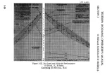
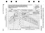
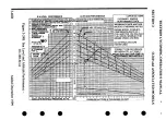
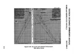
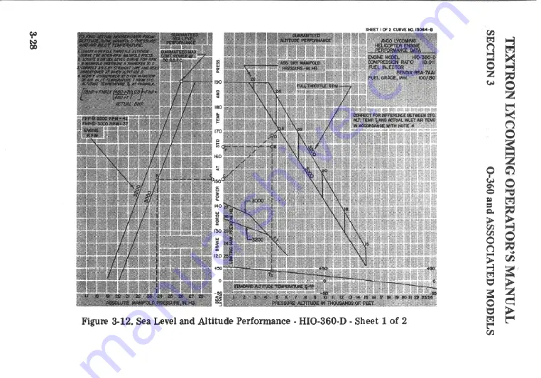
Страница 79: ...Figure 3 12 Sea Level and Altitude Performance HIO 360 D Sheet 1 of 2 ...

Страница 80: ...NOMINAL SEA LEVELPERFORMANCE ABSOLUTE MANIFOLD PRESSURE IN HD Figure 3 13 Sea Level and Altitude Performance HIO 360 D Sheet 2 of 2 ...

Страница 81: ...944 FUELFLOWVS PERCENTRATEDPOWER TEXTRONLYCOMING MODELHIO 360 ASERIES FUEL INJECTOR BENDIX RSA 5AB1 ENGINE SPEED 2900RPM MANUAL MIXTURE CONTROL TOFLOW METER GAGE 110 100 90 70 40 50 60 70 80 90 100 PERCENT RATED POWER Figure 3 14 Fuel FlowvsPercent Rated Power HIO 360 ASeries 3 30 ...

Страница 82: ...EDMODELS SECTION3 FUEL FLOWVS PERCENT RATED POWER TEXTRON LYCOMING MODEL HIO 360 B SERIES FUEL INJECTOR BENDIX RSA 5AB1 MANUALMIXTURECONTROLTO FLOWMETERGAGE ENGINESPEED 2500 2700 2900 RPM Figure 3 15 Fuel Flow vs Percent Rated Power HIO 360 B Series 3 31 ...

Страница 83: ...ATEDMODELS CURVE NO 12972 FUEL FLOW vsPERCENT RATED POWER AVCO LYCOMING ENGINE MODEL HIO 360 C SERIES FUEL INJECTOR BENDIX RSA 5ADI ENGINE SPEED 2900 RPM MANUAL MIXTURE CONTROL TOFLOWMETER GAGE Figure 3 16 Fuel Flow vs Percent Rated Power HIO 360 C Series 3 32 ...

Страница 84: ...Figure 3 17 Sea Level and Altitude Performance 0 360 A C Series except those listed for Figure 3 35 HO 366 A Series ...

Страница 85: ......

Страница 86: ...CURVENO 10819 Figure3 19 Sea LevelandAltitudePerformance 0 360 B D Series ...

Страница 87: ... TOC PERFORMANCE DATA 3 CONNECT A CBYSTRAIGHTLINEAND READ HORSEPOWER AT GIVENALTITUDED 4 MODIFY HORSEPOWERATD FORVARIATION OFAIRINETTEMPERATURE T FROM MAXIMUMPOWER MIXTURE STANDARD ALTITUDE TEMPERATURE TS UNLESS OTHERWISE NOTED BYFORMULA ALTITUDE PERFORMANCES ENGINE MODEL HO 360 BSERIES ABS DRYMANIFOLD COMPRESSION RATIO8 5 1 W HP AT D X PRESSURE IN HG COMPRESSION RATIO 8 5 1 ACTUAL H P CARBURETOR ...

Страница 88: ...CURVE NO 12700 A Figure 3 21 Sea Level and Altitude Performance IO 360 A C D J K AIO 360Series I m z C m a O ...

Страница 89: ...Figure 3 22 SeaLevel and Altitude Performance 10 360 B E F Series Excepting IO 360 B1A B1C ...

Страница 90: ...Figure 3 23 Sea Level and Altitude Performance IO 360 BlA ...

Страница 91: ...Figure 3 24 Sea Level and Altitude Performance IO 360 BlC ...

Страница 92: ...DE CURVE FOR GIVEN R PM MANIFOLD PRESS 2 LOCATE BON SEA LEVEL CURVEFOR R P M MANIFOLD PRESSURE TRANSFER TO C LYCOMING 3 CONNECTA C BY STRAIGHT LINE AND READ HORSEPOWERAT GIVEN ALTITUDE D AIRCRAFTENGINE D 4 MODIFYHORSEPOWER ATDFOR VARIATION OFAIR INLETTEMPERATURE TS FROM PERFORMANCE DATA STANDARDALTITUDE TEMPERATURE T MIXTURE ...

Страница 93: ...0 SL ALEVEL PERFORMANCE ALTITUDE PERFORMANCE CURVE NO 13549 TOFIND ACTUALHORSEPOWER FROMALTITUDE R P M MINIFOLD PRESSURE ANDAIRE INLES TEMPERTURE 0 0 ...

Страница 94: ...Figure 3 25 SeaLevel and Altitude Performance HIO 360 A Series ...

Страница 95: ...Figure 3 26 SeaLevel and Altitude Performance HIO 360 B Series ...

Страница 96: ...Figure 3 27 SeaLevel and Altitude Performance HIO 360 C Series ...

Страница 97: ...Figure 3 28 SeaLevel and Altitude Performance TIO 360 A Series Sheet 1 of 3 ...

Страница 98: ......

Страница 99: ...Figure 3 30 SeaLevel and Altitude Performance TIO 360 A Series Sheet 3 of 3 ...

Страница 100: ...TEXTRON LYCOMING OPERATOR S MANUAL O 360 and ASSOCIATED MODELS SECTION 3 Figure 3 31 Fuel Flow VB Percent Rated Power HIQ360E F Series ...

Страница 101: ...Figure 3 32 SeaLevel and Altitude Performance HIO 360 E Series ...

Страница 102: ...Figure 3 33 SeaLevel and Altitude Performance with Turbocharger Kit SK 28 121000 HI0 360 E Series ...

Страница 103: ...LS FUELFLOW VS PERCENT RATEDPOWER LYCOMING 0 360 180HPSERIES COMPRESSION RATIO 8 50 1 SPARK ADVANCE 25 BTC CURVE NO 13357 14 12 10 8 50 60 70 80 90 PERCENT RATEDPOWER 100 Figure 3 34 Fuel Flow vs Percent Rated Power 0 360 A C F G Series HO 360 C1A 3 50 RevisedMay1996 ...

Страница 104: ...D MODELS SECTION 3 Curve No 13514 FUELFLOWVS PERCENTRATEDPOWER TEXTRONLYCOMINGO 360 J145 HP COMPRESSIONRATIO 8 5 1 SPARKADVANCE 25 BTC 14 12 50 80 70 80 90 100 PERCENTRATED POWER Figure 3 34A Fuel Flow vs Percent Rated Power O 360 J2A Added May 1996 3 50A ...

Страница 105: ... w Figure 3 34B Sea Level Altitude Performanc Curve O 360 J2A ...

Страница 106: ...TEXTRON LYCOMING OPERATOR S MANUAL 0 360 and ASSOCIATED MODELS SECTION 3 Revised May 1996 3 51 ...

Страница 107: ...Figure 3 36 SeaLevelandAltitude Performance HIO 360 F Series ...

Страница 108: ...Figure 3 37 Sea Level and Altitude Performance With Turbocharger Kit SK 28 121000 HIO 360 F Series ...

Страница 109: ... 0 360 andASSOCIATED MODELS 140 CURVE NUMBER 13429 A 130 FUEL FLOW VERSUS BRAKE HORSEPOWER LYCOMING TIO 360 C1A6D 110 100 90 80 70 60 50 40 30 20 100 120 140 160 BRAKE HORSEPOWER 180 200 Figure 3 38 Fuel Flow vs Brake Horsepower TIO 360 C1A6D 3 54 ...

Страница 110: ...TEXTRON LYCOMING OPERATOR S MANUAL 0 360 and ASSOCIATED MODELS SECTION 3 2 2 3 55 ...

Страница 111: ...Figure 340 Sea Level and Altitude Performance TIO 360 CA6D ...

Страница 112: ...0 360 and ASSOCIATED MODELS TEXTRON LYCOMING OPERATOR S MANUAL SECTION 3 I S _ S s ...

Страница 113: ...e Pre Starting Inspection 4 1 Daily Pre Flight Engine 4 2 Turbocharger 4 2 25 Hour Inspection Engine 4 2 50 Hour Inspection Engine 4 3 Turbocharger 4 4 100Hour Inspection Engine 4 5 Turbocharger 4 6 400Hour Inspection Engine 4 6 Non Scheduled Inspections 4 6 ...

Страница 114: ... are meant for the engine only Consult the airframe manufacturer s handbook for additional instructions Pre Starting Inspection The daily pre flight inspection is a check of the aircraft prior to the first flight of the day This inspection is to determine the general condition of the aircraft and engine The importance of proper pre flight inspection cannot be over emphasized Statistics prove sever...

Страница 115: ...replacement should be made before the aircraft is flown 8 Check controls for general condition travel and freedom of operation 9 Induction system air filter should be inspected and serviced in accordance with the airframe manufacturer s recommendations b Turbocharger 1 Inspect mounting and connections of turbocharger for security lubricant or air leakage 2 Check engine crankcase breather for restr...

Страница 116: ...ecurity of mounting clamps and be sure connections are tight at spark plug and magneto terminals b Fuel and Induction System Check the primer lines for leaks and security of the clamps Removeand clean the fuelinlet strainers Check the mixture control and throttle linkage for travel freedom of move ment security of the clamps and lubricate if necessary Check the air intake ducts forleaks security f...

Страница 117: ...to the cylinder and if found its cause must be determined and corrected before the aircraft resumes operation Heavy discoloration and appearance of seepageat cylinder head and barrel attachment area is usually due to emission of thread lubricant used during assembly of the barrel at the factory or by slight gas leakage which stops after the cylinder has been in service for awhile This condition is...

Страница 118: ...inimum gap Check for excessive oil in the breaker compartment if found wipe dry with a clean lintless cloth The felt located at the breaker points should be lubricated in accordance with the magneto manufacturer s instructions Check magneto to engine timing Timing procedure is described in Section 5 1 h of this manual d Engine Accesories Engine mounted accessories such as pumps temperature and pre...

Страница 119: ...ValveInspection Removerocker boxcovers and check forfreedom of valve rockers when valvesare closed Look for evidence of abnormal wear or broken parts in the area of the valvetips valvekeeper springs and spring seats If any indications are found the cylinder and all of its components shouldbe removed includingthe piston and connecting rod assembly and inspected for further damage Replace any parts ...

Страница 120: ...l System Repairof FuelLeaks 5 5 Carburetor or Fuel Injector Inlet ScreenAssembly 5 5 FuelGradesand Limitations 5 5 Air Intake Ductsand Filters 5 5 Idle Speedand Mixture Adjustment 5 5 Lubrication System Oil Gradesand Limitations 5 6 Oil Suction and Oil PressureScreens 5 6 Oil PressureReliefValve 5 6 Cylinder Assembly 5 7 Generatoror Alternator Drive BeltTension 5 12 TurbochargerControl System 5 12...

Страница 121: ...ssion stroke is reached this is indicated by a positive pressure inside the cylinder tending to push the thumb off the spark plug hole Continue rotating the crankshaft until the advance timing mark on the front face of the starter ring gear is in alignment with the small hole located at the two o clock position on the front face of the starter housing Ring gear may be marked at 20 and 25 Consult s...

Страница 122: ...TEXTRONLYCOMINGOPERATOR S MANUAL SECTION 5 0 360andASSOCIATED MODELS Figure5 1 IgnitionWiringDiagrom Figure5 2 TimingMarks 4 cyl 1200Series 5 2 ...

Страница 123: ...the plug from the rotor viewing location in the center of the housing 6 Turn the rotating magnet drive shaft in direction of normal rotation until the painted tooth of the distributor gear is centered in the timing hole Observe that at this time the built in pointer just ahead of the rotor viewing window aligns with either the L or R depending on rotation 7 Hold the magneto in this position and in...

Страница 124: ... screws and cor rect Retorque breaker screws to 20 to 25 in lbs 3 Retard Breaker Removetiming lightleads fromthe mainbreaker terminals Attach one positive lead to retard breaker terminal and second positive lead to the tachometer breaker terminal if used 4 Backthe engine up a fewdegrees and againbumpforwardtoward number one cylinder firing position until pointer is aligned with 15 retard timing ma...

Страница 125: ... 40 inch pounds on carburetors and 65 70 inch pounds on fuel injectors The hex head plug on pressure carburetors is tightened to 160 175 inch pounds c Fuel Grades and Limitations The recommended aviation grade fuel for the subject engines is listed in Section 3 item 8 In the event that the specified fuel is not available at some locations it is permissible to use higher octane fuel Fuel of a lower...

Страница 126: ... check this new position byrepeating the abovepro cedure Make additional adjustments as necessary until a check results ina momentarypick upofapproximately50 RPM Each time the adjustmentis changed the engineshouldbe run up to 2000RPM to clear the engine before proceeding with the RPM check Make finaladjustment of the idle speed adjustment to obtain the desired idlingRPM with closed throttle The ab...

Страница 127: ... oil pressure within the specified limits If pressure under normal operating conditions should consistently exceed the maximum or minimum specified limits adjust the valve as follows With the engine warmed up and running at approximately 2000 RPM observe the reading on the oil pressure gage If the pressure is above maximum or below minimum specified limits stop engine and screw the adjusting screw...

Страница 128: ...lling directly away from crankcase Be careful not to allow the piston to drop against the crankcase as the piston leavesthe cylinder b Removal of Piston from Connecting Rod Remove the piston pin plugs Insert piston pin puller through piston pin assemblepuller nut then proceed to remove piston pin Do not allow connecting rod to rest on the cylinder bore of the crankcase Support the connectingrod wi...

Страница 129: ...d before the plunger is inserted e Assembly of Cylinder and Related Parts Rotate the crankshaft so that the connecting rod of the cylinder being assembled is at the top center of compression stroke This can be checked by placing two fingers on the intake and exhaust tappet bodies Rock crankshaft back and forth over top center If the tappet bodies do not move the crankshaft is on the compression st...

Страница 130: ...ching the ring compressor as it is pushed off HORIZONTAL CENTER LINEOFENGINE 3 CYLINDER HOLD DOWN PLATE INSTRUCTIONS ON ENGINES USING CYLINDER HOLD DOWN PLATES DURING INITIALTIGHTENING USE TWO SHIMSBETWEEN EACH PLATEAND THEBARREL LOCATED ASSHOWN REMOVE SHIMS BEFORE FINALTIGHTENING Figure 5 2A Location of Shims Between Cylinder Barrel and Hold Down Plates where applicable and Sequence of Tightening...

Страница 131: ...s Install shims between cylinder base hold down plates and cylinder barrel as directed in figure 5 2A and tighten 1 2 inch hold down nuts to 300 inch lbs 25 foot lbs torque using the sequence shown in figure 5 2A b Remove shims and using the same sequence tighten the 1 2 inch cylinder base nuts to 600 in lbs 50 foot lbs torque NOTE Cylinder assemblies not using hold down plate are tightened in the...

Страница 132: ...the valve rocker directly over the end of the push rod and push down so as to compress the hydraulic tappet spring While holding the spring compressed the valve clearance should be between 028 and 080 inch If clearance does not come within these limits remove the push rod and insert a longer or shorter push rod as required to correct clearance NOTE Inserting a longer push rod will decrease the val...

Страница 133: ...ler the differential pressure controller or the waste gate It is recommended that an authorized overhaul facility check these controls Exhaust Bypass Valve TIO 360 A Series This valve is actuated by engine oilpressure and is set to predetermin ed open and closed clearances These clearances and the procedures for setting them are shown in Figure 5 4 Exhaust Bypass Valve TI0 360 C1A6D This valve is ...

Страница 134: ...TEXTRON LYCOMING OPERATOR S MANUAL SECTION 5 O 360 and ASSOCIATED MODELS Figure 5 3 Density Control Full Throttle Setting Limits 5 14 ...

Страница 135: ... With60 50PS pressure in cylinder TEXTRONLYCOMINGOPERATOR S MANUAL 0 360 and ASSOCIATEDMODELS SECTION5 Figure5 4 ExhaustBypassValveOpenandClosed Setting Figure5 5 TimingMarksonRotatingMagnet 5 15 ...

Страница 136: ...TEXTRONLYCOMINGOPERATOR S MANUAL SECTION 5 0 360andASSOCIATED MODELS Figure 5 4 IgnitionWiringDiagram DualMagneto 5 16 ...

Страница 137: ...nning Failure of Engine to Develop Full Power Rough Engine Low Oil Pressure High Oil Temperature ExcessiveOil Consumption 6 1 6 2 6 2 6 3 6 4 6 4 6 4 6 5 TROUBLE SHOOTING TURBOCHARGE R ExcessiveNoise or Vibration 6 6 Engine Will Not Deliver Rated Power 6 6 Critical Altitude Lower Than Specified 6 7 Engine Surgesor Smokes 6 8 High Deck Pressure 6 8 ...

Страница 138: ...d turbochargers their probable causes and remedies TROUBLE PROBABLE CAUSE REMEDY Failure of Engine Lack of fuel to Start Overpriming Defective spark plugs Check fuel system for leaks Fill fuel tank Clean dirty lines strain ers or fuel valves Leave ignition off and mixture control in Idle Cut Off open throttle and unload engine by cranking for a few seconds Turn ignition switch on and proceed to st...

Страница 139: ...ust mixture Failureof Engine to IdleProperly Incorrect idle mixture Leak in the induc tion system Incorrect idle adjustment Unevencylinder compression Faulty ignition system Insufficient fuel pressure Mixture too rich in dicated by sluggish engineoperation red exhaust flame at night Extreme cases indicated by black smoke from exhaust Tighten all connections in the induction system Re place any par...

Страница 140: ...tions Readjustment of fuel injector or carburetor by authorized personnel is indicated Tighten all connections Replace defective parts Clean and gap or replace spark plugs Fill tank with fuel of recommended grade Clean points Check internal timing of magnetos Check wire with elec tric tester Replace defective wire Replace connectors on spark plug wire Failure of Engine to Develop Full Power Thrott...

Страница 141: ...ression Insufficient oil Low Oil Pressure Air lock or dirt inrelief valve Leakin suction line or pres sure line Highoil temperature Defectivepres sure gage Stoppage in oil pump intake pas sage Insufficient air cooling Install newmounting bushings Check compression Fill to proper levelwith recommended oil Removeand clean oil pressure relief valve Checkgasketbetween accessoryhousingand crankcase See...

Страница 142: ... caused by worn or stuck rings Examine sump for metal particles If found over haul of engine is indicated Defective tem perature gage Replace gage Excessive Oil Consumption Low grade of oil Fill tank with oil con forming to specification Failing or failed bearings Worn piston rings Incorrect installa tion of piston rings Failure of rings to seat new nitrided cyls Check sump for metal particles Ins...

Страница 143: ... Leak in engine intake or ex haust manifold Dirty impeller blades Clogged manifold system Engine will not Deliver Rated Power Clear all ducting Foreign material lodged in com pressor impeller or turbine Excessive dirt build up in com pressor Leak in engine intake or ex haust Rotating assembly bearing seizure Restriction in re turn lines from actuator to waste gate controller Disassemble and clean ...

Страница 144: ...troller not getting enough oil pressure to close the waste gate Chips under metering valve in controller holding it open SECTION6 REMEDY Have exhaust bypass control ler adjusted Tighten fittings Re place lines or hoses Increase oil pressure to desired pressure Remove inlet line at actuator and clean orifice Replace unit Low pressure Clogged orifice in inlet to actuator Butterfly shaft binding Chec...

Страница 145: ...fold Clogged breather If there is oil leakage at actuator drain clean cylinder and replace piston seal Clean and free action Bleed system Replace controller Check breather for re strictions to air flow NOTE Smoke would be normal if engine has idled for a prolonged period High Deck Pres sure Compressor Discharge Pres sure Controller meter ing valve not opening aneroid bellows leaking Exhaust bypass...

Страница 146: ... inlet If pressure on outlet side of actuator is too high have exhaust bypass controller adjusted Exhaust bypass actua tor piston locked in full closed po sition Usually accompanied by oil leakage at actuator drain line NOTE Exhaust bypass nor mally closed in idle and low power conditions Should open when actuator inlet line is disconnected Exhaust bypass con troller mal function Remove and disass...

Страница 147: ...TORAGE Page Preparationof Enginefor Installation 7 1 General Inspectionof EngineMounting 7 2 Oil and Fuel Line Connections 7 2 Preparationof Carburetorsand Fuel Injectorsfor Installation 7 2 CorrosionPreventionin Engines Installedin InactiveAircraft 7 3 ...

Страница 148: ...is not possible heat the cylinders with heat lamps before attempting to drain the engine After the oil sump has been drained the plug should be replaced and safety wired Fill the sump or external tank with lubricating oil The crankshaft should again be turned several revolutions to saturate the interior of the engine with the clean oil Wheninstalling spark plugs make sure that they are clean if no...

Страница 149: ...gnment as this can produce abnormal stresses with the engine Attacbing Engine to Mounts See airframe manufacturer s recommendations for method of mounting the engine Oil and Fuel Line Connections The oil and fuel line connections are called out on the accompanying installation drawings Propeller Installation Consult the airframe manufacturer for information relative to propeller installation 2 PRE...

Страница 150: ...Injector Bendix Remove and clean the fuel inlet strainer assembly and reinstall Inject clean fuel into the fuel inlet connection with the fuel outlets uncapped until clean fuel flows from the outlets Do not exceed 15 psi inlet pressure CORROSION PRE VENTION IN ENGINES INSTALLED IN INACTIVE AIRCRAFT Corrosion can occur especially in new or overhauled engines on cylinder walls of engines that will b...

Страница 151: ...zzle before spraying cylinders d With the crankshaft stationary again spray each cylinder through the spark plug holes with approximately two ounces of corrosion preventive oil Assemble spark plugs and do not turn crankshaft after cylinders havebeen sprayed The corrosion preventive oil to be used in the foregoing procedure should conform to specification MIL L 6529 Type 1 heated to 200 F 220 F 93 ...

Страница 152: ...TEXTRON LYCOMING OPERATOR S MANUAL 0 360 and ASSOCIATED MODELS SECTION 7 7 5 ...

Страница 153: ...SECTION7 0 360 and ASSOCIATEDMODELS SLICK 4100 SERIESMAGNETO 4200 SERIESMAGNETO Figure 7 2 Magneto Connections 7 6 ...

Страница 154: ...5625 18 NF 3 FOR CONNECTING 375FLARED TUBE COUPLING OILFROM COOLER 375 18 NPT CAN BEROTATED TOANY RADIAL POSITION OIL TOCOOLER 750 16 NF3 FOR CONNECTING FLARED TUBE COUPLING TEXTRONLYCOMINGOPERATOR S MANUAL 0 360 and ASSOCIATED MODELS SECTION 7 OIL TO COOLER 375 18 NPT THERMOSTATIC OIL BY PASS VALVE Figure 7 3 Oil Cooler Connections 7 7 ...

Страница 155: ...m Figure 7 4 Installation Drawing 0 360 A B Series 0 r ...

Страница 156: ...Figure7 5 Installation Drawing 0 360 AIC 10 360 B1C ...

Страница 157: ...FITTING OIL PRESS SCREEN HSG OILFROM COOLER MAGNETO ACCESSORY OILRETURN PROP GOV DRIVE PAD SEE FIG7 2FOR MAGNETO CONNECTIONS SEEFIG 7 3FOR OPTIONAL CONNECTIONS Figure 7 6 Installation Drawing 0 360 C D Series Excepting C2B C2D ...

Страница 158: ... SEE FIG7 3FoC OPTIONAL CONECTONS ...

Страница 159: ...Figure 7 8 Installation Drawing 10 360 A Series ...

Страница 160: ...Figure 7 9 Installation Drawing 10 360 B1A ...

Страница 161: ...Figure 7 10 Installation Drawing 10 360 B1B BID ...

Страница 162: ...Figure 7 11 ...

Страница 163: ...MAGNETO TYPE S4LN 200 I Figure 7 12 Installation Drawing HIO 360 A1A ...

Страница 164: ...ACHOMETER CONNECTION BREATHER FITTING OILTEMPERATURE CONN OIL PRESS SCREEN HSG OIL FROM COOLER MAGNETO TYPE S4LN 200 m z SEEFIG 7 3FOROPTIONAL CONNECTIONS Figure 7 13 Installation Drawing HIO 360 B1A B1B ...

Страница 165: ...ABLES Page Table of Limits Ground Run After Top Overhaul Flight Test After Top Overhaul Full Throttle HP at Altitude Table of Speed Equivalents Centigrade Fahrenheit Conversion Table Inch Fraction Conversions 8 1 8 2 8 3 8 4 8 4 8 5 8 6 ...

Страница 166: ...AND INFORMATION CONCERNING TOLERANCES AND DIMENSIONS THAT MUST BE MAINTAINED IN TEXTRON LYCOMING AIRCRAFT ENGINES CONSULT THE LATEST EDITION OF SPECIAL SERVICE PUBLICATIONNO SSP 1776 CONSULT LATEST EDITION OF SERVICE INSTRUCTION NO 1029 FOR INFORMATION PERTINENT TO CORRECTLY INSTALLING CYLINDER ASSEMBLY Revised December 1999 8 1 ...

Страница 167: ...0 LL TEXTRON LYCOMING OPERATOR S MANUAL SECTION 8 0 360 and ASSOCIATED MODELS ...

Страница 168: ...fuel R uel L carb R carb AmbAir Left Right Climb Cruise Adjustments Required After Flight After Test Flight 1 Make careul visual inspection of engine s 2 Check oil level s Z 3 If oil consumption is excessiv see operator s C manual for limits then remove spark plugs and check cylinder barrels for scoring ...

Страница 169: ... 17 500 18 000 18 500 19 000 70 8 68 3 65 8 63 4 61 0 58 7 56 5 54 3 53 1 52 1 51 4 50 0 19 500 20 000 20 500 21 000 21 500 22 000 22 500 23 000 23 500 24 000 24 500 15 000 49 1 48 0 47 6 46 0 45 2 44 0 43 3 42 2 41 4 40 3 39 5 38 5 TABLE OF SPEED EQUIVALENTS Sec Mi M P H Sec Mi M P H Sec Mi M P H 72 0 60 0 51 4 45 0 40 0 36 0 32 7 30 0 27 7 25 7 50 60 70 80 90 100 110 120 130 140 24 0 22 5 21 2 2...

Страница 170: ... 10 14 0 137 78 280 536 0 17 8 0 32 0 143 33 290 554 0 12 22 10 50 0 148 89 300 572 0 6 67 20 68 0 154 44 310 590 0 1 11 30 86 0 160 00 320 608 0 4 44 40 104 0 165 56 330 626 0 10 00 50 122 0 171 11 340 644 0 15 56 60 140 0 176 67 350 662 0 21 11 70 158 0 182 22 360 680 0 26 67 80 176 0 187 78 370 698 0 32 22 90 194 0 193 33 380 716 0 37 78 100 212 0 198 89 390 734 0 43 33 110 230 0 204 44 400 752...

Страница 171: ... 366 43 64 1875 0276 4 762 11 16 2187 0376 5 556 23 32 2344 0431 5 593 47 64 25 0491 6 350 3 4 2812 0621 7 144 25 32 2969 0692 7 540 51 64 3125 0767 7 937 13 16 3437 0928 8 731 27 32 3594 1014 9 128 55 64 375 1105 9 525 7 8 4062 1296 10 319 29 32 4219 1398 10 716 59 64 4375 1503 11 112 15 16 4687 1725 11 906 31 32 4844 1842 12 303 63 64 5 5312 5469 5625 5937 6094 625 6562 6719 6875 7187 7344 75 78...

Отзывы: