MOUNTING AND WIRING INSTRUCTIONS
NOTE: Underwriters Laboratories (UL) does not require all fixtures to have ground wires. These fixtures
meet all UL specifications.
1. Turn off power at circuit box to avoid possible electric shock.
2. Beginning at sides and working at an angle, peel protective coating (if applicable) from face plate
(A) (see fig. 1).
3. Remove retaining screws (B) from top of face plate (A) or cap nuts (B1) from face plate (A) and
separate mounting plate (C) from face plate (A).
4. Position flat side of mounting plate (C) against wall at mounting location and mark outer holes (D)
with a pencil.
NOTE: Mounting plate (C) must be level for fixture to hang straight.
5. Drill a 1/8 inch hole at each pencil mark then insert wall anchors (E) by gently tapping with a
hammer.
6. Thread outlet box wires through center opening in mounting plate (C).
7. Position mounting plate (C) with outer holes (D) over wall anchors (E) and secure with screws (K) or
FIXTURE ASSEMBLY INSTRUCTIONS
Warning: This fixture is for indoor use only.
1. Replace face plate (A) over mounting plate (C) and secure with retaining screws (B) or cap nuts (B1).
2. Place glass shade(s) (L) into holder(s) (M) and secure with retaining ring(s) (O) or thumb screws (N1)
(if applicable).
3. Turn power back on at circuit box.
All rights reserved.
Made in China
WARRANTY INFORMATION
ASSEMBLY INSTRUCTIONS FOR INDOOR LIGHTING FIXTURE
NOTE:
Carefully unpack fixture and parts. Make sure all parts are included before discarding any
packing materials (see figure 1).
WARNING:
ELECTRICAL SHOCK CAN RESULT IN SERIOUS INJURY.
Read and follow instructions exactly as shown. If instructions are unclear, do not proceed.
Contact a qualified electrician. Read all instructions before beginning. Proper wiring is
essential for safe operation of this fixture. When cutting or drilling into walls or ceilings, do not
damage electrical wiring, gas lines, or water lines. If any of the fixture or wiring components
are damaged, do not install fixture. Return to place of purchase.
For fixtures provided with 75° C or 90° C supply wire warning only. (These warnings are
provided on the U.L. label and on the fixture carton.) Risk of fire. Most dwellings built before
1985 have supply wires rated 60° C. Consult a qualified electrician before installing.
Owner’s Manual
LED Indoor Lighting Fixture
Installation Instructions
Guide d’utilisation
Instructions d’installation
Appareil d’éclairage pour utilisation intérieure avec LED
GARANTIE LIMITÉE DE CINQ ANS
MISE EN GARDE: L’ÉLECTROCUTION POURRAIT CAUSER DE GRAVES BLESSURES PERSONNELLES.
Lisez ces instructions et suivez-les exactement comme illustré. En cas de doute, ne commencez
pas l’installation. Consultez un électricien qualifié. Lisez toutes les instructions avant de
commencer l’installation. Un câblage approprié est essentiel au bon fonctionnement de cet
appareil d’éclairage. Lorsque vous faites une entaille ou que vous percez un trou dans un mur
ou un plafond, n’endommagez pas les câbles électriques, les canalisations de gaz ou d’eau. Si
l’un des composants de raccordement ou de l’appareil d’éclairage est endommagé, n’installez
pas cet appareil d’éclairage. Retournez-le à l’endroit où vous l’avez acheté.
Convient uniquement aux appareils comportant un avertissement indiquant que l’appareil
d’éclairage est doté d’un fil supportant une chaleur de 75°C ou 90°C. (Ces avertissements se
trouvent sur l’étiquette U.L. et sur l’emballage de l’appareil d’éclairage.)
LES INSTRUCTIONS D’ASSEMBLAGE DE L’APPAREIL D’ÉCLAIRAGE POUR UTILISATION INTÉRIEURE
NOTA : Déballez soigneusement l’appareil d’éclairage et les pièces. Assurez-vous que toutes les pièces
y sont avant de mettre l’emballage au rebut (voir fig. 1).
WARNING
Turn off electricity to the mounting site before beginning installation.
Mounting instructions must be followed exactly as shown for the fixture to be safely
supported.
CLEANING AND CARE
To clean, wipe fixture with soft cloth. Clean glass with mild soap. Spray from chemical cleaners can
discolor the finish of fixture. Do not use scouring pads, powders, steel wool or abrasive paper to
clean this fixture.
NOTE FOR FIXTURES THAT ARE SOLID BRASS:
Your hand-crafted, solid brass lighting fixture has been coated with a durable, baked-on acrylic
lacquer which gives maximum protection against the weather. However, in time the brightness of
the brass will tarnish, giving way to an authentic old-world brass finish. To keep your solid brass
fixture looking new for years to come, regularly apply a good quality, non-abrasive car wax to all
metal surfaces, giving the fixture an extra protective covering.
ORDERING PARTS
Keep this manual for future reference, and in case replacement parts are needed. Available parts can
be ordered from place of purchase. Use exact wording from diagrams when ordering parts.
FIGURE 2.
FIXTURE
WIRES:
Black
HOUSE
WIRES:
Black
(Hot)
HOUSE
WIRES:
White
(Neutral)
HOUSE
WIRES:
Bare
Copper
(Ground)
FIXTURE
WIRES:
Bare
Copper
(Ground)
FIXTURE
WIRES:
White
*NOT SUPPLIED
Line art shown may not exactly match the
fixture enclosed. However, the installation
instructions do apply to this fixture.
FIGURE 1.
CAP NUTS (B1)
RETAINING
RING (O)
GLASS
SHADE (L)
HOLDER (M)
THUMB
SCREWS (N1)
FACE
PLATE (A)
GREEN
GROUNDING
SCREW (H)
SIDE
HOLE (I)
OUTLET BOX
SCREWS (P)
RETAINING
SCREW (B)
MOUNTING
HOLES (F)
MOUNTING
PLATE (C)
SCREW (K)
*GROUND
WIRE
WIRE
CONNECTORS (G)
OUTER
HOLE (D)
WALL
ANCHORS (E)
*OUTLET
BOX (J)
*NON FOURNI
Il est possible que le dessin illustré ici ne
soit pas la reproduction exacte de l’appareil
d’éclairage contenu dans la boîte.
Les instructions d’installation demeurent
cependant valables.
FIGURE 1.
LA BAGUE DE
RETENTION (O)
TROUS
EXTERIEURS (D)
ECROUS
CAPUCHONS (B1)
ABAT-JOUR
EN VERRE (L)
SUPPORT (M)
VIS A CLE (N1)
PLAQUE
AVANT (A)
VIS DE MISE
A LA TERRE
(VERTE) (H)
TROU
LATERAL (I)
VIS DE LA BOITE
DE SORTIE DE
COURANT (P)
PLAQUE DE
FIXATION (C)
VIS (K)
*FIL DE MISE
A LA TERRE
CONNECTEURS
DE FIL (G)
PIECE D’ANCRAGE
MURALE (E)
*BOITE DE SORTIE
DE COURANT (J)
LA BAGUE DE
RETENTION (B)
TROUS DE
FIXATION (F)
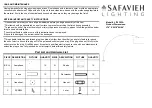
NOTE: THIS FIXTURE IS SUITABLE FOR USE WITH DIMMABLE SWITCHES, SEE BELOW FOR LIST OF
COMPATIBLE DIMMERS.
Brand Model # DIMMING RATING
Lutron CTCL-153PDH-WH, MACL-153MR-WH, SCL-153PR-WH, 10-100%
TGCL-153PH-WH, DVCL-153P, S-600P
Leviton IPL06, 6674, IPI06, 6631 10-100%
Not recommended for use with motion sensors, light sensors, timers or any other external controls.
Congratulations on your purchase. This fixture has been designed to give you many years of
beauty and service.
Félicitations ! Vous avez acheté un produit
.
Cet appareil d’éclairage a été conçu pour durer de
nombreuses années.
secure mounting plate (C) to outlet box (J) with outlet box screws (P) (if applicable).
8. Identify color coding of fixture wires (see fig. 2).
9. Connect the black wire from the fixture with the black wire (live wire) from the outlet box by wire
connector (G), and wrap the wire connector (G) with electrical tape for a more secure connection.
10. Connect the white wire from the fixture with the white wire (neutral wire) from the outlet box by
wire connector (G), and wrap the wire connector (G) with electrical tape for a more secure connection.
11. Partially thread green grounding screw (H) into side hole (I) on mounting plate (C) (see fig.1.)
12. Wrap grounding wire from fixture around green grounding screw (H) leaving enough excess wire,
then connect the excess grounding wire from the fixture with the grounding wire from outlet box
by wire connector (G) (if applicable), then wrap the wire connector (G) with electrical tape for a
more secure connection.
13. Tighten green grounding screw (H). Do not over tighten.
14. Tuck wires inside outlet box (J).