background image

Part No. F40BP75010005 

Form No. BP7501-5

Revision: 05252021 

U.L. Model No.: CF784-3

Printed in China 

05/2021

SERIAL NUMBER: 

DATE CODE:

The serial number of this fan can be found on the nameplate on top of the fan housing. The date code can be found on 

the carton and on top of the fan housing, stamped in ink on a white label. You should record this data above and keep 

it in a safe place for future use.

Questions, problems, missing parts: Before returning to the store, Call Customer Service

1-800-777-4440

www.luminancebrands.com

Retain this manual for future use.

370 Falls Commerce Pkwy.

Cuyahoga Falls, OH 44224

Содержание kathy ireland HOME CARRERA CF784BS03

Страница 1: ...CF784BS03 Brushed Steel CF784ORB03 Oil Rubbed Bronze CF784SW03 Satin White Net Weight 28 4 Lbs Model Numbers Espa ol p gina 23 Fran ais page 45 READ AND SAVE THESE INSTRUCTIONS TRANSITIONAL R 1 800 77...

Страница 2: ...about electrical wiring have your fan installed by a licensed electrician NOTE This fan is suitable for use with solid state speed controls NOTE All set screws must be checked and re tightened where n...

Страница 3: ...r 1 D Switch Housing 1 E Switch Housing Assembly 1 F Hanger Bracket 1 G Hanger Ball 4 5 Downrod Assembly 1 H Flange Sets 5 I Blade Sets 5 HARDWARE BAG CONTENTS Part Description Quantity 1 Threaded Stu...

Страница 4: ...ry mount fan to outlet box marked Acceptable for Fan Support of 22 7 kg 50 lbs or less and use screws supplied with outlet box Most outlet boxes commonly used for support of light fixtures are not acc...

Страница 5: ...re Flange Gasket is supplied in the loose parts bag if required 3 3 Mount Flanges to Blades using Four 10 24 x 10mm Washer Head Blade Screws Figure 3 A spare 10 24 x 10mm Washer Head Blade Screw is su...

Страница 6: ...Y FLANGE INTERLOCKING FEATURE FLANGE INTERLOCKING FEATURE Figure 5 3 5 NOTE Each blade flange assembly must have the flange gasket in place between each of the assemblies The Flanges have an Interlock...

Страница 7: ...using Assembly Secure the Switch Housing Assembly by reinstalling the Three 8 32 x 12mm Flat Head Screws previously removed Figure 7 Proceed to Ceiling Fan Assembly Step 3 9 To avoid possible fire or...

Страница 8: ...n in the motor coupler is properly installed and the set screws securely tightened Failure to verify that the pin and set screws are properly installed could result in the fan falling WARNING THREE 80...

Страница 9: ...rpin Clip must be properly installed to prevent the Clevis Pin from working loose Pull on the Downrod to make sure the Clevis Pin is properly installed It is critical that the clevis pin in the motor...

Страница 10: ...alled in the Motor Coupler Cover then slide the Motor Coupler Cover on the Downrod until it rests on the Motor Housing Be sure the Motor Coupler Cover is oriented correctly Figure 14 CEILING COVER DOW...

Страница 11: ...curely tighten the Set Screw in the Hanger Ball NOTE A loose set screw could create fan wobble It is critical that the pin in the hanger ball is properly installed and the set screw securely tightened...

Страница 12: ...ttach the Hanger Bracket to the Outlet Box using the two screws supplied with the Outlet Box Figure 19 Hanger bracket must seat firmly against outlet box If the outlet box is recessed remove wall boar...

Страница 13: ...re using Wire Connector supplied Figure 22 This product is designed to use only those parts supplied with this product and or any accessories designated specifically for use with this product by Lumin...

Страница 14: ...ITE WIRES GREEN WIRES Figure 24 5 4 After connections have been made turn Wires upward and carefully push Wires into the Outlet Box with the White and Green Wires on one side of the Outlet Box and pos...

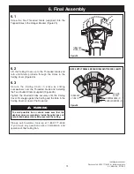
Страница 15: ...o the Threaded Studs and turn until Studs protrude through the Holes in the Ceiling Cover Figure 26 6 3 Secure the Ceiling Cover in place by sliding Lockwashers over the Threaded Studs and installing...

Страница 16: ...n the opposite direction and reverse the airflow 7 Using Your Ceiling Fan REVERSE SWITCH SWITCH HOUSING ASSEMBLY Figure 27 7 2 Check the operation of the fan by gently pulling on the pull chain switch...

Страница 17: ...be installed or mounted in the middle of the room and at least 7 feet above the floor and 18 inches from the walls If ceiling height allows install the Fan 8 9 feet above the floor for optimal airflow...

Страница 18: ...U L Model No CF784 3 18 11 Repair Parts 1 4 3 16 2 22 17 21 8 7 13 10 PARTS BAG 7 4 10 11 13 9 6 5 8 12 15 14 18 19 20 11 9 9 5 6...

Страница 19: ...acket 2 Hanger Ball 1 3 Downrod 4 5 Parts Bag Containing 764687 CHM 764687 BLX 764687 CHM 4 Threaded Studs 2 5 Lockwashers 2 6 Knurled Knobs 2 7 Pin Clevis 8 Clip Hairpin 9 Screw Flat Head 8 32 x 12mm...

Страница 20: ...ub are tight 4 Wire connectors inside switch housing 4 Check to make sure wire connectors in switch rattling housing are not rattling against each other or against the interior wall of the switch hous...

Страница 21: ...inance Brands Ceiling Fan Product component or Luminance Brands Ceiling Fan Product accessory caused by normal wear and tear rather than due to defects in materials or workmanship Loss or damage resul...

Страница 22: ...e fan housing The date code can be found on the carton and on top of the fan housing stamped in ink on a white label You should record this data above and keep it in a safe place for future use Questi...

Страница 23: ...0 pulgadas CF784BS03 Acero cepillado CF784ORB03 Bronce aceitado CF784SW03 Blanco satinado Peso neto 28 5 lb N meros de modelo LEA Y GUARDE ESTAS INSTRUCCIONES TRANSICIONAL Fran ais page 45 English pag...

Страница 24: ...l usuario y gu rdelo para referencia futura 2 Tenga cuidado con el ventilador y las paletas cuando limpie el ventilador lo pinte o trabaje cerca de l Apague siempre el suministro el ctrico al ventilad...

Страница 25: ...dor 1 conjunto 1 12 Kit de equilibrado de las paletas 1 1 1 Aseg rese de que ha recibido las siguientes piezas NOTA Si no est seguro acerca de la descripci n de una pieza consulte la ilustraci n del p...

Страница 26: ...egura y ser capaz de resistir una carga de por lo menos 50 libras Si su ventilador va a reemplazar a un accesorio de iluminaci n de techo existente DESCONECTE la electricidad en la caja de fusibles pr...

Страница 27: ...dor utilizando cuatro tornillos con cabeza de arandela para paleta n m 10 24 x 10 mm Figura 3 Se incluye un tornillo de repuesto con cabeza de arandela n m 10 24 x 10 mm suministrado en la bolsa de pi...

Страница 28: ...pesta a debe tener la empaquetadura para pesta a colocada entre cada uno de los ensamblajes Las pesta as para paleta tienen un dispositivo de interbloqueo que se debe acoplar completamente antes de ap...

Страница 29: ...firmemente la carcasa del interruptor reinstalando los tres tornillos de cabeza plana n m 8 32 x 12 mm retirados previamente Figura 8 Vaya a Ensamblaje del ventilador de techo Paso 3 9 SWITCH HOUSING...

Страница 30: ...loje el tornillo que sujeta el cable verde de conexi n a tierra SETSCREW LOOSENED HANGER BALL 4 5 DOWNROD PIN GREEN GROUND WIRE Figura 10 THREE 80 MOTOR LEADS UNTWISTED 4 5 DOWNROD Figura 11 3 11 Sepa...

Страница 31: ...e la varilla descendente para asegurarse de que el pasador de horquilla est instalado correctamente 4 5 DOWNROD MOTOR COUPLING RETIGHTEN SETSCREWS RETIGHTEN SETSCREWS 3 13 Mientras jala hacia arriba l...

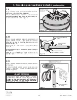
Страница 32: ...cubierta sobre la varilla descendente hasta que descanse sobre la carcasa del motor Aseg rese de que la cubierta del acoplador del motor est orientada correctamente Figura 14 CEILING COVER DOWNROD Fi...

Страница 33: ...dr a causar oscilaci n del ventilador 3 Ensamblaje del ventilador de techo continuaci n HANGER BALL DOWNROD ASSEMBLY 6 to 9 INCHES 3 17 El ventilador viene con cables de conexi n de color azul negro y...

Страница 34: ...para soportar ventiladores de 22 7 kg 50 lb o menos y utilice los tornillos de montaje suministrados con la caja de tomacorriente La mayor a de las cajas de toma corriente que se utilizan com nmente p...

Страница 35: ...5 1 Conecte el cable verde de conexi n a tierra procedente de la esfera de suspensi n y el cable verde de conexi n a tierra procedente del soporte de suspensi n al conductor de conexi n a tierra de su...

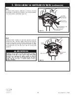
Страница 36: ...nterior de la caja de tomacorriente con los cables de conexi n de color blanco y verde en un lado de dicha caja y posicione el cable de conexi n negro negro azul en el otro lado de la caja de tomacorr...

Страница 37: ...estriados suministrados Figura 26 Apriete de manera segura los pomos estriados hasta que la cubierta del techo quede bien ajustada contra el techo y la varilla descendente no toque el agujero ubicado...

Страница 38: ...DE TIRO DEL INTERRUPTOR DE 3 VELOCIDADES ACOPLADOR DE CADENA COLGANTE FUNDIDO A PRESI N 7 1 Restablezca la alimentaci n el ctrica a la caja de tomacorriente conectando la electricidad en la caja de fu...

Страница 39: ...as de las paredes Si la altura del techo lo permite instale el ventilador a 8 a 9 pies por encima del piso para lograr una circulaci n de aire ptima Consulte a su minorista Luminance Brands para infor...

Страница 40: ...No de modelo U L CF784 3 40 11 Piezas de repuesto 1 4 3 16 2 22 17 21 8 7 13 10 PARTS BAG 7 4 10 11 13 9 6 5 8 12 15 14 18 19 20 11 9 9 5 6 BOLSA DE PIEZAS...

Страница 41: ...dente de 4 5 pulg 1 Bolsa de piezas que contiene 764687 CHM 764687 BLX 764687 CHM 4 Esp rrago roscado 2 5 Arandela de seguridad 2 6 Pomo estriado 2 7 Pasador de horquilla 8 Clip de horquilla 9 Tornill...

Страница 42: ...ntaci n el ctrica principal est APAGADA ADVERTENCIA 3 El ventilador oscila excesivamente 1 Los tornillos de ajuste ubicados en el acoplamiento del motor est n flojos 2 El tornillo del ensamblaje de es...

Страница 43: ...te del Producto de Ventilador de Techo Luminance Brands o accesorio del Producto de Ventilador de Techo Luminance Brands por causa del desgaste por el uso normal en lugar de por causa de defectos de m...

Страница 44: ...ciones ubicada encima de la carcasa del ventilador El c digo de fecha se puede encontrar en la caja de cart n y encima de la carcasa del ventilador estampado en tinta en una etiqueta blanca Usted debe...

Страница 45: ...F784BS03 Acier bross CF784ORB03 Bronze huil CF784SW03 Blanc satin Poids net 28 4 lbs Num ros des mod les LISEZ ET CONSERVEZ CES INSTRUCTIONS TRANSITIONAL Espa ol p gina 23 English page 1 Questions pro...

Страница 46: ...ion du ventilateur REMARQUE Ce ventilateur est appropri pour emploi avec des commandes de vitesse semi conducteurs REMARQUE Toutes les vis de pression doivent tre inspect es et resserr es lorsque cela...

Страница 47: ...Ensemble de bo tier de l interrupteur 1 F Support de suspension 1 G Ensemble de tige de suspension descendante de 4 5 po avec rotule 1 H Brides de fixation des pales du ventilateur 5 I Pales du venti...

Страница 48: ...e ou du panneau des disjoncteurs ce moment et retirez le luminaire existant Votre nouveau ventilateur de plafond n cessitera une ligne d alimen tation lectrique mise la terre de 120 volts c a 60 Hz da...

Страница 49: ...ides de fixation des pales sur les pales du ventilateur en utilisant quatre vis t te embase pour pale N 10 24 x 10 mm Figure 3 Un vis t te embase pour pale N 10 24 x 10 mm est fourni dans le sac de pi...

Страница 50: ...t de bride de fixation en place entre chacun des ensembles Les brides de fixation des pales comportent une fonction de verrouillage qui doit tre totalement enclench e avant de serrer la vis Assurez vo...

Страница 51: ...tateur S curisez le bo tier de l interrupteur en r installant les trois vis t te plate N 8 32 x 12 mm qui avaient t retir es auparavant Figure 8 Passez maintenant l tape 3 9 de cette section consacr e...

Страница 52: ...rotule de la tige de suspension en vue de leur r installation lors de l tape 3 16 REMARQUE Ne pas desserrer la vis tenant en place le fil de mise la terre vert SETSCREW LOOSENED HANGER BALL 4 5 DOWNRO...

Страница 53: ...pour vous assurer que l axe d paule ment est install correctement paulement est install correctement 4 5 DOWNROD MOTOR COUPLING RETIGHTEN SETSCREWS RETIGHTEN SETSCREWS 3 13 Tout en tirant sur la tige...

Страница 54: ...e de suspension descendante jusqu ce qu il repose sur le bo tier du moteur Assurez vous que le cache du coupleur du moteur est orient correctement Figure 14 CEILING COVER DOWNROD Figure 15 3 15 Placez...

Страница 55: ...de pression desserr e pourrait faire osciller le ventilateur 3 Assemblage du ventilateur de plafond suite HANGER BALL DOWNROD ASSEMBLY 6 to 9 INCHES 3 17 Le ventilateur est fourni avec des fils bleu...

Страница 56: ...sol Figure 18 MISE EN GARDE Pour r duire le risque d incendie de choc lectrique ou de blessure montez le ventilateur sur le bo tier de prises de courant comportant l indication suivante Acceptable fo...

Страница 57: ...gaine isolante de couleur verte Raccordez solidement les fils avec les capuchons de connexion de fils fournis Figure 21 5 Comment effectuer le c blage pour raccorder votre ventilateur de plafond Pour...

Страница 58: ...t effectuer le c blage pour raccorder votre ventilateur de plafond suite 5 4 Apr s la r alisation des connexions retournez les conducteurs vers le haut et enfoncez d licatement les conducteurs l int r...

Страница 59: ...ure 26 6 3 Assujettissez la monture de plafond sa place en faisant glisser les rondelles de blocage par dessus les goujons filet s et en installant les deux boutons molet s fournis Figure 26 Serrez au...

Страница 60: ...A NETTE DE TIRAGE DE L INTERRUPTEUR TROIS VITESSES DISPOSITIF DE COUPLAGE DE LA CHA NETTE PENDANT MOUL SOUS PRESSION 7 1 R tablissez l alimentation lectrique de la prise de courant en allumant l lectr...

Страница 61: ...nd d importantes conomies suppl mentaires pourraient tre r alis es la fois sur le plan nerg tique et sur le plan financier gr ce ce simple geste teignez le ventilateur lorsque vous sortez de la pi ce...

Страница 62: ...Mod le U L N CF784 3 62 11 Pi ces de rechange 1 4 3 16 2 22 17 21 8 7 13 10 PARTS BAG 7 4 10 11 13 9 6 5 8 12 15 14 18 19 20 11 9 9 5 6 SAC DE PI CES...

Страница 63: ...655 17 761655 32 761655 92 1 Support de suspension 2 Rotule de la tige de suspension 1 3 Tige de suspension descendante 4 5 po Sac de pi ces contenant 764687 CHM 764687 BLX 764687 CHM 4 Goujon filet 2...

Страница 64: ...mani re excessive 1 Les vis de pression du coupleur du moteur ne sont peut tre pas serr es correctement 2 La vis de pression de l ensemble de rotule de la tige de suspension tige descendante n est pe...

Страница 65: ...entilateur ou Produit pour un ventilateur de plafond Luminance Brands ou un accessoire d un Ventilateur ou Produit pour un ventilateur de plafond Luminance Brands caus s par l usure normale plut t que...

Страница 66: ...Mod le U L N CF784 3 66 Notes Notas Remarques...

Страница 67: ...luminancebrands com Veuillez t l phoner au 1 800 777 4440 pour toute assistance compl mentaire Mod le U L N CF784 3 67 Notes Notas Remarques...
Страница 68: ...tier du ventilateur Le code de date figure sur le carton et en haut du bo tier du ventilateur Il est estamp l encre sur une tiquette blanche Il faut enregistrer ces informations et les conserver en l...

Отзывы: