background image


English 

18


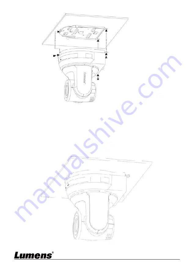
4.2.2.7 How to remove 

1.  Remove the connecting wires from the camera 

2.  Uninstall the camera together with the ceiling, loosen the three screws 

that fix the metal plates A and B and push to the left to remove the 

machine 


3.  Then remove the screws on the hanger and the machine 

black 

screw


Содержание VC-A70H

Страница 1: ...0H PTZ Video Camera Installation Guide English Important To download the latest version of Quick Start Guide multilingual user manual software or driver etc please visit Lumens https www MyLumens com support ...

Страница 2: ... 5 2 Setting Menu 22 Chapter 6 Descriptions of Major Functions 29 6 1 I would like to switch to VC A70H 29 6 2 I would like to set the Digital Output RGB YUV 29 6 3 I would like to enable the Tally Mode function 29 6 4 I would like to hide the preset image switch Motionless Preset 29 6 5 I would like to save the current lens position data 30 6 6 I would like to clear the saved position data 30 6 7...

Страница 3: ...rotate the image 32 6 15 I would like to change the camera direction 32 6 16 I would like to display the current status 32 6 17 I would like to reset to the original setting 32 Chapter 7 DIP Switch Setting 34 7 1 DIP SWITCH 34 7 2 RS 422 Connection 36 Chapter 8 Troubleshooting 38 Supplier s Declaration of Conformity 47 CFR 2 1077 Compliance Information 40 ...

Страница 4: ... product Lumens Digital Optics Inc hereby reserves the right to make changes to product specifications without prior notice The information in this file is subject to change without prior notice To fully explain or describe how this product should be used this manual may refer to names of other products or companies without any intention of infringement Disclaimer of warranties Lumens Digital Opti...

Страница 5: ...ct by yourself Opening or removing covers may expose you to dangerous voltages and other hazards Refer all servicing to licensed service personnel 1 11 Unplug the PTZ Video Camera from the wall outlet and refer servicing to licensed service personnel when the following situations happen If the power cords are damaged or frayed If liquid is spilled into the Product or the Product has been exposed t...

Страница 6: ...ed and found to comply with the limits for a Class A computer device pursuant to Article 15 J of FCC Rules These limits are designed to provide reasonable protection against harmful interference in a residential installation This digital apparatus does not exceed the Class A limits for radio noise emissions from digital apparatus as set out in the interference causing equipment standard entitled D...

Страница 7: ...monitored controlled and supported over a standard Ethernet network In order to enable IP Link network connectivity and control you must install and configure an IP Link enabled device such as a MediaLink controller or IP Link Ethernet control interface To download an IP Link driver for this product please visit http www extron com driverdownloads ...

Страница 8: ... 7 Chapter 2 Package Contents VC A70H Instruction for installation Remote Control Power Cord Power Adapter RS 422 Connector Appearance may vary depending on country region Metal Plate A Metal Plate B M3 Screws ...

Страница 9: ... RS 232 input 12 RS 422 Connection 13 HDMI Output 3 2 Description of LED indicator 3 2 1Power 3 2 1 1 No Light Power off 3 2 1 2 Green light In use 3 2 1 3 Flickering green Signal from the remote control is received the indicator flickers every 0 5 second 3 2 2Standby 3 2 2 1 Orange In standby mode 3 2 2 2 No Light Power on 3 2 2 3 Green light HDBaseT and HDMI are connected 3 2 2 4 No Light HDBase...

Страница 10: ... in the box are complete or not Please contact the supplier for any shortage and make sure to keep the accessories in the box intact 4 1 3 Please choose a proper place for installation of VC A70H in advance Please determine an installation place according to the following requirements 4 1 1 1 Confirm the position for the object to be captured 4 1 1 2 Confirm whether the VC A70H is set at a proper ...

Страница 11: ...e camera on a flat desk directly to ensure the normal vertical and horizontal operation of the machine 4 2 2 I would like to install VC A70H on the ceiling 4 2 2 1 Prepare for the parts and equipment required during the installation 1 Accessories of VC A70H in the box metal plates A B M3 screw silver x 8 black x 2 2 Screw for locking on ceiling mounted hanger x 4 3 Drilling machine screw driver la...

Страница 12: ...English 11 4 2 2 2 Camera Size Length x Width x Height 174 x 186 8 x 170 8 mm Weight 2 0 Kg 4 2 2 3 Max rotation dimension of camera ...

Страница 13: ...English 12 4 2 2 4 Size Diagram 1 Metal plate B ceiling side Metal plate B locking screw Metal plate B locking bolt ...

Страница 14: ...English 13 Metal plate B ceiling side M3 threaded hole M3 threaded hole M3 threaded hole ...

Страница 15: ...English 14 2 Metal plate A machine side Metal plate A machine side Metal plate A locking screw ...

Страница 16: ...English 15 3 Bottom of machine ...

Страница 17: ... of the lens 3 The machine including metal plates is weighed at about 2 5 kg If it is to be installed on the ceiling please use the hanger that has obtained UL security approval to prevent the machine from falling down 4 Please check whether the camera is installed securely on a regular basis 4 2 2 6 Installation steps 1 Please adjust resolution on DIP switch at first Remark Please refer to Chapte...

Страница 18: ...as obtained UL security approval 2 Please reserve the hole for the connecting wires of the camera 4 Combine the metal plate A and the metal plate B 1 Push the metal plate A up to the ceiling and then to the right to latch the metal plate B 2 And then secure with 2 M3 silver screws and 1 M3 black screw ...

Страница 19: ...onnecting wires from the camera 2 Uninstall the camera together with the ceiling loosen the three screws that fix the metal plates A and B and push to the left to remove the machine 3 Then remove the screws on the hanger and the machine black screw ...

Страница 20: ... 3 1 1 Connecting to an HDTV computer monitor HDMI 4 3 1 2 Connecting to a HDBaseT Adapter PoE Power Supply is available for this device HDBaseT Adapter may be enabled without connecting to a power cord HDMI Cable Monitor or HDTV HDBaseT Cable HDBaseT Adapter ...

Страница 21: ...nnection between VCs RS 232 in out Remark With RS 232 in out at most 7 VCs can be connected 4 3 2 2 Connecting to one computer for connection between VCs RS 422 Remark Please refer to 7 2 RS 422 connection for the RS 422 connection instructions Remark With RS 422 at most 7 VCs can be connected ...

Страница 22: ...length Focus Auto Auto focus Freeze Freeze the screen Home Enter Go back to the main page Execute Info Status information L R Direction Set L R Direction OFF Normal Menu Display OSD menu Mirror Rotate the image OFF Mirror Flip Mirror Flip Pan Tilt Reset Clear the Pan Tilt setting Picture Switch image effect OFF B W Power Power Switch Preset Appoint an ID 0 9 to save the current position data Reset...

Страница 23: ...mode setting Exposure_ Comp On Off AE Level Exposure_ Comp Level 7 C 7 The value can be adjusted only after Exposure_ Comp is activated Spot Light On Off The value can be adjusted when the mode is set to Shutter Pri Spot Light Position X 0 15 Y 0 15 The value can be adjusted only after Spot Light is activated Shutter Pri 59 94 29 97 mode 50 25 mode Shutter priority setting 1 10000 1 10000 1 6000 1...

Страница 24: ...1 125 1 120 1 100 1 100 1 90 1 75 1 60 1 50 1 30 1 25 1 15 1 12 1 8 1 6 1 4 1 3 1 2 1 2 1 1 1 1 Iris Pri 1 F1 8 2 F2 3 F2 4 4 F2 8 5 F3 4 6 F4 7 F4 8 8 F5 6 9 F6 8 10 F8 11 F9 6 12 F11 13 F14 14 Close Iris setting ...

Страница 25: ... dB Manually set the gain Manual Speed 59 94 29 97 mode 50 25 mode Manually set the shutter 1 10000 1 10000 1 6000 1 6000 1 4000 1 3500 1 3000 1 2500 1 2000 1 1750 1 1500 1 1250 1 1000 1 1000 1 725 1 600 1 500 1 425 1 350 1 300 1 250 1 215 1 180 1 150 1 125 1 120 1 100 1 100 1 90 1 75 1 60 1 50 1 30 1 25 1 15 1 12 ...

Страница 26: ...F2 4 4 F2 8 5 F3 4 6 F4 7 F4 8 8 F5 6 9 F6 8 10 F8 11 F9 6 12 F11 13 F14 14 Close Manually set the aperture Bright 1 C 28 Gain Limit 1 9 dB 2 12 dB 3 15 dB 4 18 dB 5 21 dB 6 24 dB 7 27 dB 8 30 dB 9 33 dB Max limit value of electron gain WDR 1 OFF 2 1 3 2 4 3 WDR settings ...

Страница 27: ...ush trigger R Gain 0 C 255 Adjustable when the white balance mode is set to Manual B Gain 0 C 255 Adjustable when the white balance mode is set to Manual Picture Picture effect 1 Off 2 B W Set the picture effect Sharpness 1 A 16 Adjust the sharpness of the image NR 1 Off 2 1 3 2 4 3 5 4 6 5 Noise reduction setting Saturation 0 A 14 Adjustable when the image mode is set to Custom mode Hue 0 A 14 Ad...

Страница 28: ...cond 3 300 per second Set the rotation speed of the cradle head when Preset is executed Dig Effect Mirror 1 Off 2 Mirror 3 Flip 4 Mirror Flip Set the mode at which the image is turned Auto Focus AF Sensitivity 1 Low 2 Normal Select the AF triggering speed The higher the speed is the faster AF is triggered AF speed 1 Normal 2 1 3 2 4 3 5 4 6 5 Focus speed after AF triggering System Prompt On Off Tu...

Страница 29: ...ode 1 Low 2 Height 3 Off Turn on off the Tally Mode to set the brightness of indicator PD Address 1 C 255 The Protocol set to PD allows the camera ID address to be assigned Output Mode 1 3840x2160 29 97p 2 3840x2160 25p 3 1920x1080 59 94p 4 1920x1080 50p 5 1920x1080 59 94i 6 1920x1080 50i 7 1280x720 59 94p 8 1280x720 50p Set the image output mode Digital Output YUV RGB Set the digital output Facto...

Страница 30: ...ct Digital Output 5 Press ENTER to activate 6 Press or to select YUV RGB 7 Press MENU to exit 6 3 I would like to enable the Tally Mode function 1 Press MENU to activate the setting menu 2 Press or to select System 3 Press ENTER to activate 4 Press or to select Tally Mode 5 Press ENTER to activate 6 Press or to select Low High Off 7 Press MENU to exit 6 4 I would like to hide the preset image swit...

Страница 31: ...27 6 7 I would like to turn on the back light compensation function 1 Press Back Light on the remote control to turn on or turn off the back light compensation Note Enabled only when the Exposure Mode is set to Full Auto 6 8 I would like to adjust the shooting angle of the lens 1 Press Tilt or Tilt on the remote control to adjust the angle upward or downward 2 Press Pan or Pan on the remote contro...

Страница 32: ...iggering speed of focus The higher the speed is the faster focus is triggered To shoot fast moving objects AF Sensitivity can be set to High or Medium which is applicable to quick focus When the environment is too dark to enable auto focus or fixed objects have to be shot in different brightness AF Sensitivity can be set to Low 1 Press MENU to activate the setting menu 2 Press or to select Auto Fo...

Страница 33: ...reeze the current image on the display 6 14 I would like to rotate the image 1 Press Mirror on the remote control to switch Off Mirror Flip Mirror Flip 6 15 I would like to change the camera direction 1 Press L R Direction Set on the remote control to switch L R Direction Off Normal 6 16 I would like to display the current status 1 Press Info on the remote control to display the current status inf...

Страница 34: ...English 33 6 Press or to select On 7 Press ENTER to execute ...

Страница 35: ... turn off the machine before changing DIP switch setting 7 1 DIP SWITCH 7 1 1 OUTPUT Switch Output Mode Setting Output Mode Setting 3840 2160 29 97p 3840 2160 25p 1920 1080 59 94p 1920 1080 50p 1920 1080 59 94i 1920 1080 50i 1280 720 59 94p 1280 720 50p ...

Страница 36: ...etting Function Descriptions 0 7 ID 0 7 8 9 Reserved 7 1 4 System Switch Setting Function Descriptions DIP 1 RS 232C RS 422 selector OFF RS 232C ON RS 422 DIP 2 Infrared signal output switch OFF Off ON On DIP 3 Communication baud rate selector OFF 9600 ON 38400 DIP 4 Reserved ...

Страница 37: ...XD OUT 5 GND 6 RXD IN 7 RXD IN 8 TXD IN 9 TXD IN Note Please connect IN to OUT when connecting to SONY products For non SONY products it may be necessary to connect IN to OUT 7 2 2 Use RS 422 Connection 1 Hold the two sides of RS 422 connector and pull out in the direction shown by the arrow in the figure below ...

Страница 38: ...WG Nos 28 to 18 and insert it into the connector hole then use flat screw driver to fix it 3 Insert the wired RS 422 connector back to the camera Now the connection is completed Note When RS 422 connection is being used do not use RS 232C connection ...

Страница 39: ... after changes to DIP Switch setting After completing DIP Switch setting unplug and reconnect the power cord and turn on the machine to change the setting 5 VC A70H cannot be operated by remote control 1 Please confirm if the Camera Select on the remote control can be used together with the IR Select on VC A70H 2 Please prevent VC A70H from direct sunshine 3 Make sure the energy saving bulb and th...

Страница 40: ...English 39 7 The device cannot be controlled with RS 232 RS422 1 Make sure the connection is correct RS 232 422 Input 2 Make sure System Switch DIP 1 and DIP 3 are correct ...

Страница 41: ...ormation Supplier Lumens Integration Inc 4116 Clipper Court Fremont CA 94538 United States e mail support mylumens com FCC Compliance Statement This device complies with Part 15 of the FCC Rules Operation is subject to the following two conditions 1 This device may not cause harmful interference and 2 this device must accept any interference received including interference that may cause undesired...

Отзывы: