Full product range & more information:
www.lumenalights.com
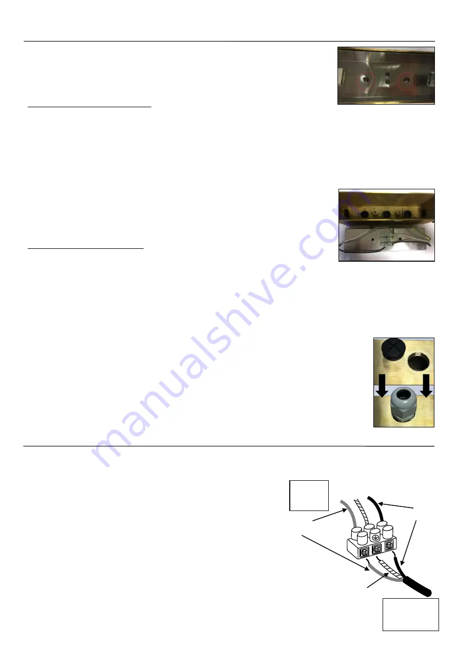
Light
Fitting
N
L
Live Cables
Earth
Cable
Mains
Power Cable
Neutral Cables
Earth Cable
Earth = Yellow & Green
Neutral = Blue
Live = Brown
INSTALLATION:
•
Remove the front plate by unscrewing and removing the 2 x brass screws.
•
Remove the inner Reflector Box (attached to the bulb holders) by unscrewing
and removing the 2 x screws in the centre (see pic. A).
•
Continue below based on your selected installation method.
Brick Replacement
–
NEW WALL
•
Select which cable inlet will be used for the mains cable input on the brass mounting box based on existing cable
location. A hole can be drilled in the centre of the inlet to allow the cable to pass through OR unscrew and remove the
cable inlet completely and replace with an M20 Cable Gland (see pic. C).
•
Build the brass mounting box into the brick wall (a wooden frame can also be used to support the fitting if the brick is a
different size
–
attach mounting box to the frame via the 2 x screw holes on the edge of the brass back box
–
height of
brackets can be adjusted slightly).
Ensure a sufficient amount of cable has been pulled through the selected
cable inlet for wiring.
•
Wire the mains cable to the connector block located on the back of the reflector box (see pic. B & wiring instructions).
•
Replace the reflector box and screw in place with the two screws removed
earlier. Ensure no cables are trapped between the reflector and mounting box.
•
Install 2 x G9 lamps.
•
Replace the front plate and secure in place with the 2 x brass screws removed initially,
ensuring the foam seal is in place behind the face plate.
Recess into flat surface (cut out)
•
Cut out the hole for the mounting box (masonry, decking etc).
Mounting Box dimensions approx. (L)198 x (W) 55 x (D) 60mm, excludes side bracket and cable glands.
•
Select which cable inlet will be used for the mains cable input on the brass mounting box based on existing cable
location. A hole can be drilled in the centre of the inlet to allow the cable to pass through OR unscrew and remove the
cable inlet completely and replace with an M20 Cable Gland (see pic. C).
•
Hold the brass mounting box in position and mark the 2 x screw holes on either side of the box. The height of these
brackets can be adjusted slightly, if required, by loosening the two screws holding them in place.
•
Remove the mounting box. For masonry installation, drill and install wall plugs. For wood installations, pilot hole can be
drilled if required. M4 screws recommended.
•
Pull a sufficient amount of cable through the prepared cable inlet / gland for easier wiring.
•
Secure the mounting box in place with relevant screws, as per above.
•
Wire the mains cable to the connector block located on the back of the reflector box (see
pic. B and wiring instructions below).
•
Replace the reflector box and screw in place with the two screws removed earlier. Ensure no
cables are pinched between the reflector and mounting box.
•
Install 2 x G9 lamps.
•
Replace the front plate and secure in place with the 2 x brass screws removed initially, ensuring the
foam seal is in place behind the face plate.
WIRING / CONNECTION:
NOTE:
240v cable located outside must be armoured or laid inside
armoured conduit / trunking.
•
Locate the mains electrical supply (pre-installed armoured cable).
•
Ensure the mains power is switched off.
•
Connect the fitting to the connector block located on the back of the
reflector (See pic. B).
•
Ensure all terminals of the connector block are secure with no stray
wires and that the connection is watertight. Self-amalgamating tape
wrapped around the cable will help seal the hole in the cable inlet if a
cable gland is not used. Ensure M20 Cable Gland is tight and secure.
•
Once fully installed, turn on the mains power.
A
B
C


