background image

INSTRUKCJA OBSŁUGI - SZYBKI  START

Pełna wersja instrukcji dostępna na

Full version of user’s manual available at  

www.lumel.com.pl

USER’S MANUAL - QUICK START

PL

EN

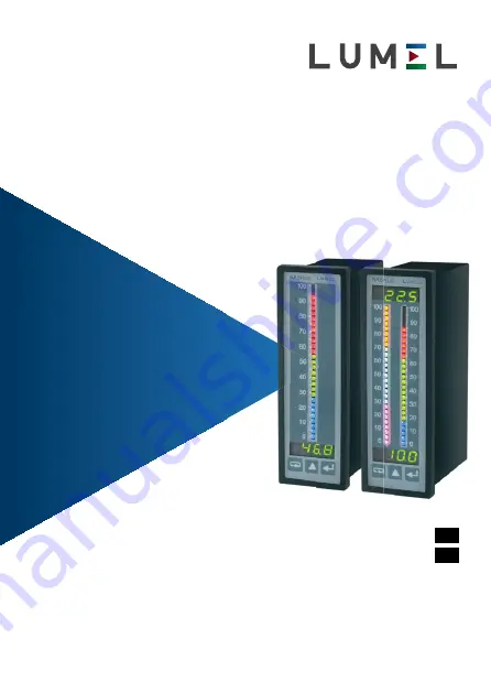
MIERNIK CYFROWO-ANALOGOWY

Z WIELOKOLOROWYM BARGRAFEM

DIGITAL-TO-ANALOGUE METER 

WITH A MULTICOLOUR BARGRAPH

NA5

PLUS, 

NA6

PLUS

Содержание NA5PLUS

Страница 1: ...sja instrukcji dost pna na Full version of user s manual available at www lumel com pl USER S MANUAL QUICK START PL EN MIERNIK CYFROWO ANALOGOWY Z WIELOKOLOROWYM BARGRAFEM DIGITAL TO ANALOGUE METER WI...

Страница 2: ...dpowiada wymaga niom normy PN EN 61010 1 Uwagi dotycz ce bezpiecze stwa Monta u i instalacji po cze elektrycznych powinna dokonywa osoba z wymaganymi uprawnieniami do monta u urz dze elektrycznych Oso...

Страница 3: ...sygna w wej cio wych wyj ciowych oraz interfejsu RS482 przewodami o przekroju do 2 5 mm2 Wymiary miernika przedstawia Rys 1 W przypadku uszkodzenia miernik mo e by naprawiany wy cznie przez serwis aut...

Страница 4: ...zo nej na wy wietlaczu i bargrafie Na bargrafie zaznaczone s r wnie progi alarmowe w zale no ci od nastaw parametr w alarmowych oraz rozdzielczo ci i typu bargrafu Miernik automatycznie wygasza niezna...

Страница 5: ...duje wej cie do trybu programowania Tryb programowania jest za bezpieczony kodem bezpiecze stwa seC Naci ni cie i przytrzymanie przez oko o trzy sekundy przycisku po woduje wej cie do menu podgl du i...

Страница 6: ...k nie wy wietlenie napisu err poruszanie si po matrycy wej cie do wybranego poziomu wej cie do zmian parametru wyj cie z matrycy programowania kasowanie wyj alarmowych Pomiar 3 s menu podgl du Wy wiet...

Страница 7: ...cie do wybranego poziomu wej cie do zmian parametru wyj cie z matrycy programowania kasowanie wyj alarmowych Pomiar 3 s menu podgl du Wy wietlanie warto ci minimalnej CH1 Wy wietlanie warto ci maksym...

Страница 8: ...trybu programowania Rysunek 7 przedstawia matryc przej w trybie programowania Przyciskiem porusza si po grupach parametr w g wnych np Chn bAr AL1 AL2 itd dla NA5PLUS oraz Ch1 Ch2 bAr1 bAr2 AL1 AL2 it...

Страница 9: ...OFF 00 0 00 5 00 5 00 5 5 wygaszenie nieznacz cych zer zmiana migaj cej pozycji zmiana migaj cej pozycji zmiana migaj cej pozycji zmiana migaj cej pozycji 00 0 00 5 00 5 00 5 00 5 500 zmiana migaj ce...

Страница 10: ...grafu kolor bargrafu dolny pr g wskaza bargrafu g rny pr g wskaza bargrafu dolny pr g alarmu g rny pr g alarmu typ alarmu op nienie alarmu podtrzyma nie alarmu kolor dolnego znacznika alarmu kolor g r...

Страница 11: ...typ alarmu op nienie alarmu podtrzyma nie alarmu kolor dolnego znacznika alarmu kolor g rnego znacznika alarmu Warto zmiany sygna u mierzo nego czas zmiany sygna u mierzo nego kana wej ciowy ch ka in...

Страница 12: ...rezystancja wej ciowa 4 Pomiar pr du 5 5 A rezystancja wej ciowa 10 m 10 Nat enie pr du p yn cego przez rezystor termometryczny 400 A Rezystancja przewod w cz cych rezystor termometryczny z mierni kie...

Страница 13: ...B d podstawowy 0 1 zakresu pomiarowego 1 cyfra 0 2 zakresu pomiarowego 1 cyfra dla termoelement w R S T B dy dodatkowe w znamionowych warunkach u ytkowania kompensacji zmian temperatury spoin odniesie...

Страница 14: ...j cia binarne Pob r mocy 13 VA Waga 0 4 kg Wymiary 48 X 144 X 100 mm Kompatybilno EMC odporno na zak cenia zgodnie z PN EN 61000 6 2 emisja zak ce zgodnie z PN EN 61000 6 4 Wymagania odno nie bezpiecz...

Страница 15: ...Sygna wyj ciowy analogowy brak 0 pr dowy 0 4 20 mA 1 napi ciowy 0 10 V 2 2 x pr dowy 0 4 20 mA 3 2 x napi ciowy 0 10 V 4 pr dowy 0 4 20 mA i napi ciowy 0 10 V 5 Wyj cia alarmowe brak 0 4 wyj cia prze...

Страница 16: ...ygna wyj ciowy analogowy brak 0 pr dowy 0 4 20 mA 1 napi ciowy 0 10 V 2 2 x pr dowy 0 4 20 mA 3 2 x napi ciowy 0 10 V 4 pr dowy 0 4 20 mA i napi ciowy 0 10 V 5 Wyj cia alarmowe brak 0 4 wyj cia przeka...

Страница 17: ...e device The user must take them into account when the operation of the device does not meet the user s expectations Possible consequences when these instructions are not followed Safety instructions...

Страница 18: ...STALLATION 2 1 Fitting The NA5PLUS and NA6PLUS meter is designed to be mounted on a panel For this purpose a 44 0 x 137 5 mm hole should be prepa red in the panel The thickness of the material from wh...

Страница 19: ...the measured value on the display and the bar graph Depending on alarm parameters settings the resolution and bar graph type alarm thresholds are also displayed on the bar graph The meter blanks autom...

Страница 20: ...uses entering the programming mode The programming mode is secured with the seC security code Pressing and holding the key for about 3 seconds causes entering the menu of the preview and the menu of r...

Страница 21: ...s Correct password programming matrix yes no display of the inscription err Matrix navigation entrance to the selected level entry to parameter changes exit from the programming matrix resetting of al...

Страница 22: ...password entry mode seC 3 s Correct password programming matrix yes no display of the inscription err Matrix navigation entrance to the selected level entry to parameter changes exit from the program...

Страница 23: ...7 shows the trans ition matrix in the programming mode The key allows for moving around the main parameters groups e g Ch1 bAr1 AL1 AL2 etc for NA5PLUS and Ch1 Ch2 bAr1 bAr2 AL1 AL2 etc for NA6PLUS Pr...

Страница 24: ...amples of changing the value of the selected parameter parameter symbol Example of changing the value of the selected parameter with a fixed decimal point numeric parameter Example of changing the val...

Страница 25: ...ar graph indication upper threshold of bar graph indication lower alarm threshold upper alarm threshold alarm type alarm delay holding up the alarm colour of the lower alarm marker colour of the upper...

Страница 26: ...ar graph indication upper threshold of bar graph indication lower alarm threshold upper alarm threshold alarm type alarm delay holding up the alarm colour of the lower alarm marker colour of the upper...

Страница 27: ...resistance 4 Current measurement 5 5 A input resistance 10 m 10 Current flowing through the resistance thermometer 400 A Resistance of conductors linking the resistance thermometer with the meter 20 w...

Страница 28: ...digit 0 2 of measuring range 1 digit for thermocouples R S T Additional errors in rated operating conditions compensation of reference joints temperature changes 1 C compensation of lead resistance c...

Страница 29: ...utputs Power consumption 13 VA Weight 0 4 kg Dimensions 48 x 144 x 100 mm EMC compatibility immunity to interference in accordance with EN 61000 6 2 interference emission in accordance with EN 61000 6...

Страница 30: ...lack 0 0 4 20mA 1 0 10 V 2 2 x 0 4 20 mA 3 2 x 0 10 V 4 1 x 0 4 20 mA 1 x 0 10 V 5 Additional output lack 0 4 relays 4 8 outputs of OC type 8 Supply voltage 95 253 V a c d c 2 20 40 V a c 20 60 V d c...

Страница 31: ...Analog output lack 0 0 4 20mA 1 0 10 V 2 2 x 0 4 20 mA 3 2 x 0 10 V 4 1 x 0 4 20 mA 1 x 0 10 V 5 Additional output lack 0 4 relays 4 8 outputs of OC type 8 Supply voltage 95 253 V a c d c 1 20 40 V a...

Страница 32: ...nania miernika PE 230V AC N 24 V DC 600 V 40 mA 5 A GND 300 mV R 600 V 40 mA 5 A GND 300 mV R GND RS 485 B A OUT 2 OUT 1 GND OC8 RL4 OC7 OC6 RL3 OC5 OC4 RL2 OC3 OC2 RL1 OC1 16 15 14 13 12 11 10 9 8 7...

Страница 33: ...61010 1 p 6 10 standard 8 9 10 1 2 3 R loop 1 loop 2 8 9 10 1 2 3 Loop 1 loop 2 R 9 10 loop 1 loop 2 2 3 Loop 1 loop 2 10 11 12 13 3 4 5 6 GND 600 V loop 1 loop 2 10 11 12 13 3 4 5 6 GND 300 mA loop...

Страница 34: ...L3 RL2 RL1 28 29 30 31 32 33 34 35 4 wyj cia przeka nikowe 23 24 25 26 AN2 AN1 wyj cia ci g e napi ciowe pr dowe 20 21 22 GND B A interfejs RS 485 MODBUS Wej cie napi ciowe 10 V 600 V Wej cie pr dowe...

Страница 35: ...PL EN 35...

Страница 36: ...lechowska 1 65 022 Zielona G ra Poland tel 48 68 45 75 100 fax 48 68 45 75 508 www lumel com pl Pracownia system w automatyki tel 68 45 75 228 45 75 117 Wzorcowanie tel 68 45 75 161 e mail laboratoriu...

Отзывы: