background image

EN

18

Designation

Description

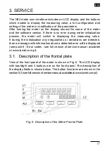
L1

The upper (main) line of the display has 6 characters used 

to display a measuring value or a parameter value during 

the meter configuration.

L2

The lower (auxiliary) line of the display has 5 characters 

used to display a measuring value, not converted by the 

individual  characteristic  or,  according  to  configuration,  a 

unit or current time.

k

The kilo symbol means that the displayed value is divided 

by a thousand, e.g. when the setting is displayed, the illu-

minated symbol means that the given value is a thousand 

times greater. For example, 1.2 kA means 1200 A

Z1

Measuring  value  averaging  indicator.  Illuminated  avera-

ging indicator informs that the set measuring value avera-

ging period has not elapsed yet.

M

The mega symbol means that the displayed value is di-

vided by a million, e.g. when the setting is displayed, the 

illuminated symbol means that the given value is a million 

times greater. For example, 3.5 MW means 3,500,000 W.

ALI

Alarm status field. This field contains the indicator informing 

about  the  alarm  status.  Illuminated  alarm  indicator  means 

that an alarm event is in progress and the relay correspon-

ding to the alarm is activated. Flashing symbol means that 

the alarm state is saved (if the alarm memory is activated).

B1...B4

Meter operation buttons. The description of the button fun-

ctions and their various combinations are shown in section 

5.2.(see full version of service manual - available at www.

lumel.com.pl)

The lower line of the display can be configured to display the unit, where 

the  unit  is  automatically  adapted  to  the  displayed  value  of  measured 

quantity and depends on set indication range. For example, if a shunt 

with a rated range greater than 1000 A is connected, the current will be 

displayed in kilo amperes (kA).

Additionally,  the  lower  line  can  display  a  selected  value  of  measured 

quantity (measured or calculated quantities) or the current time.

Содержание N32H

Страница 1: ...digital panel meter N32H instrukcja obs ugi szybki start Pe na wersja instrukcji dost pna na Full version of user s manual available at www lumel com pl user s manual quick start PL EN Zeskanuj mnie Z...

Страница 2: ...winien by wy cznik lub wy cznik automatyczny umieszczony w pobli u urz dzenia atwo dost pny dla operatora i odpowiednio oznakowany Demonta uk adu elektronicznego miernika w trakcie trwania umowy gwara...

Страница 3: ...m2 Widok miernika od strony z cz awiono na rys 5 G rna listwa przy czeniowa wyst puje opcjonalnie w zale no ci osa enia miernika Rys 3 Gabaryty miernika 96 48 N32U Instrukcja obs ugi 4 2 Schemat pod c...

Страница 4: ...laniem warto ci mierzonej pe ne skonfigurowanie miernika i ustawienie lub zmodyfikowanie ka dego z dost pnych parametr w Podczas uruchamiania miernika na wy wietlaczu zostaje wy wietlona nazwa miernik...

Страница 5: ...dzielona przez tysi c np podczas wy wietlania nastawy zapalony symbol oznacza e dana warto jest tysi c razy wi ksza Np 1 2 kA oznacza pr d 1200 A Z1 Znacznik u redniania warto ci mierzonej wiecenie zn...

Страница 6: ...zycisku powoduje wy wietlenie warto ci minimalnej na czas 2 sekund a nast pnie powr t do wy wietlania warto ci mierzonej Przycisk zwi kszania warto ci Poruszaniesi pomenu zwi kszaniepozycjidanegomenu...

Страница 7: ...przez wy wietlenie stosownego komunikatu 3 3 Programowanie parametr w miernika Programowanie parametr w miernika mo liwe jest poprzez interfejs RS485 oraz poprzez bezpo redni edycj parametr w z wykorz...

Страница 8: ...akceptacji aby przej do parametr w danej grupy Analogicznie jak wyb r grupy dokonuje si wyboru parametru kt rego warto ma zosta zmodyfiko wana W przypadku rezygnacji ze zmiany parametru opuszczenie tr...

Страница 9: ...pozycja punktu dziesi tnego Funkcja dolnego wiersza wy wietlacza wyb r wielko ci wy wietlanej w dolnym wierszu Wyb r wielko ci steruj cej stanem alarmu Wyb r typu alarmu Dolny pr g zmiany stanu alarmu...

Страница 10: ...p w Pierwszym etapem jest ustawienie cyfr oraz ustawienie znaku zgodnie z wy ej opisanym algorytmem Drugim etapem kt ry rozpoczyna si po naci ni ciu przycisku akceptacji jest ustawienie pozycji punktu...

Страница 11: ...ia bocznika Bocznik do 77 mV 150 150 mV 75 mV Bocznik do 153 mV 300 300 mV 150 mV Bocznik do 305 mV 600 600 mV 300 mV Bocznik do 610 mV 1200 1200 mV 600 mV Bocznik powy ej 610 2400 2400 mV 1500 mV Pom...

Страница 12: ...ka Trzy przeka niki ze stykiem prze cznym opcja 6A 250 V a c 6A 30V d c 0 15A 250 V d c Maksymalny pr d za czania 10A 20 ms Wyj cie analogowe Wyj cie napi ciowe Zakres znamionowy 0 10 V Maksymalne nap...

Страница 13: ...no elektromagnetyczna Odporno na zak cenia elektromagnetyczne wg PN EN 61000 6 2 Emisja zak ce elektromagnetycznych wg PN EN 61000 6 4 Wymagania bezpiecze stwa wed ug normy PN EN 61010 1 Izolacja mi d...

Страница 14: ......

Страница 15: ...uld be installed in the building or facility It should be located near the device easily accessible by the operator and suitably marked Removal of the meter electronics during the warranty period void...

Страница 16: ...a ony jest w dwie roz czne listwy przy czeniowe um pod czenie przewod w o przekroju do 2 5 mm2 Widok miernika od str przedstawiono na rys 5 G rna listwa przy czeniowa wyst puje opcjonalnie w od wyposa...

Страница 17: ...wy wietlacz LCD oraz przyciski kt re stanowi interfejs u ytkownika i umo liwiaj poza wy wietlaniem warto ci mierzonej pe ne skonfigurowanie miernika i ustawienie lub zmodyfikowanie ka dego z dost pnyc...

Страница 18: ...lluminated symbol means that the given value is a million times greater For example 3 5 MW means 3 500 000 W ALI Alarm status field This field contains the indicator informing about the alarm status I...

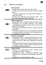
Страница 19: ...s Pressing the button during a normal operation displays a minimum value for 2 seconds then the display returns to displaying a measuring value Increase value button Navigating the menu increasing the...

Страница 20: ...e 3 3 Programming meter parameters Programming meter parameters is possible via the RS485 interface and by direct edition of the parameters using the buttons and the meter display Direct programming p...

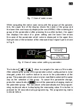
Страница 21: ...y wietlacza wy wietla nazw grupy natomiast dolny wiersz wy wietla ca y czas napis MENU Po wej ciu do grupy parametr w po naci ni ciu przycisku akceptacji g rny wiersz wy wietla warto danej nastawy nat...

Страница 22: ...ne Selection of quantity controlling the alarm state Selection of alarm type Alarm state change lower threshold Alarm state change upper threshold Alarm activation delay Alarm deactivation delay Activ...

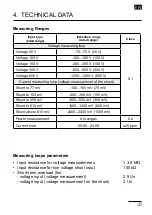
Страница 23: ...asurement of the shunt Shunt to 77 mV 150 150 mV 75 mV Shunt to 153 mV 300 300 mV 150 mV Shunt to 305 mV 600 600 mV 300 mV Shunt to 610 mV 1200 1200 mV 600 mV Shunt above 610 mV 2400 2400 mV 1500 mV P...

Страница 24: ...hree relays with a switching contact option 6 A 250 V AC 6A 30 V DC 0 15A 250 V DC Maximum switching current 10A 20 ms Analog output Voltage output Rated range 0 10 V Maximum output voltage 15 V Minim...

Страница 25: ...3 mm Electromagnetic compatibility Noise immunity acc to EN 61000 6 2 Noise emission acc to EN 61000 6 4 Safety requirements acc to EN 61010 1 Circuit to circuit insulation basic Installation category...

Страница 26: ...p to 2 5 mm2 The view of the meter from the con nectors side is shown in Fig 4 The upper terminal strip is optional and depends on the accessories of the meter The circuits of successive groups of the...

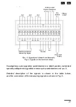
Страница 27: ...czenia sygna w mierzonych przedstawiono na rys 6 Zacisk Funkcja Opis Rys 4 Separacja galwaniczna w mierniku N32H Rys 5 Sygna y na listwach zaciskowych Analog output Measuring intputs Supply Binary out...

Страница 28: ...contact 15 16 Zasilanie Power supply Przy cze zasilania miernika Zakres napi zasilaj cych akceptowany przez miernik wynika bezpo rednio z kodu wy kona Przed instalacj miernika nale y sprawdzi czy zakr...

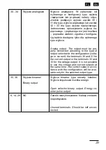
Страница 29: ...o perly connected according to the type of output selected in the configuration volta ge or current the terminals 30 and 31 for the current output or the terminals 32 and 33 for the voltage output It...

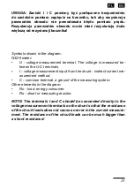
Страница 30: ...tod po redni C zacisk wsp lny masa uk adu pomiarowego Pozosta e elementy na schemacie Ro obci enie odbiornik energii Rs bocznik lub rezystor pomiarowy UWAGA Zaciski I i C powinny by pod czone bezpo re...

Страница 31: ...age is measured be tween the U C terminals I voltage measurement input from the shunt indirect current me asurement method C common terminal a ground of the measuring system Other elements in the diag...

Страница 32: ...8 45 75 508 www lumel com pl Export department tel 48 68 45 75 130 45 75 131 45 75 132 e mail export lumel com pl Calibration Attestation e mail laboratorium lumel com pl Technical support tel 48 68 4...

Отзывы: