


INSTALLATION INSTRUCTIONS
SURFACE MOUNT
ADJUSTABLE SPOTLIGHT
LUMASCAPE ASIA PACIFIC
Brisbane Technology Park, 18 Brandl Street, Eight Mile Plains, QLD 4113, Australia
Phone +61 7 3854 5000 | Fax +61 7 3854 5001 | Email: [email protected] |
www.lumacape.com
LUMASCAPE NORTH AMERICA
1300 Industrial Road, Unit #19, San Carlos, CA 94070, USA
Phone +1 650 595 5862 | Fax +1 650 595 5820 | Email: [email protected] |
www.lumacape.com
Products and specifications are subject to change without notice.
USA I Australia I Asia I Middle East I Europe
2 / 3
IN0189 N181205
Centria
C2
LS2020
DXF files are for visual reference only.
Dimensions subject to change without notice.
Please refer to instructions available at
www.lumascape.com
LS####
100mm
DXF files are for visual reference only.
Dimensions subject to change without notice.
Please refer to instructions available at
www.lumascape.com
LS####
100mm
DXF files are for visual reference only.
Dimensions subject to change without notice.
Please refer to instructions available at
www.lumascape.com
LS####
100mm
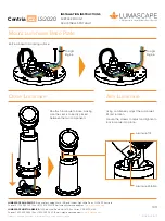
Connect the cables from the LED driver to
the terminal block on the base plate.
Wire Up Terminal Block
Install Cable Gland
Ø16mm
Drill Bit
To Light
Engine
To Light
Engine
DXF files are for visual reference only.
Dimensions subject to change without notice.
Please refer to instructions available at
www.lumascape.com
LS####
100mm
To Light
Engine
Insert the gland, ensuring
o-ring is firmly in place.
Feed supply cable
through gland and
tighten. Outer
diameter of cable
should be Ø5-10mm.
Connect supply
cable to terminal
block.
Drill the hole for the gland.
Use a 16mm drill bit to drill
the gland hole.
Colour
Designation
Blue
Neutral
Green
Earth
Brown
Active
Orange
Data
or Grey
Outer Cable
Ø5-10mm
O-Ring
Conductor colours shown are for a
standard Lumascape leader cable.
To Light Engine