background image

173100085 EN

(Original instruction manual)

Edition 07.2017

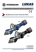
Instruction manual for rescue equipment

Multifunction tools e100 and le100  

replaces 10.2015

e100

le100

TM

Содержание STRONGARM e100

Страница 1: ...173100085 EN Original instruction manual Edition 07 2017 Instruction manual for rescue equipment Multifunction tools e100 and le100 replaces 10 2015 e100 le100 TM...

Страница 2: ...100 14 5 2 Operating the star grip 15 6 Cutting spreading spread open doors lifting 15 6 1 Safety notes 15 6 2 Cutting 16 6 3 Spreading 17 6 4 Spreading open doors 19 6 5 Lifting 21 7 Accessories 22 7...

Страница 3: ...2 Technical data 33 12 1 StrongArm e100 le100 34 12 2 Noise emission 35 12 3 Operating and storage temperature ranges 35 12 4 Oscillation vibration 35 12 5 Torque specification and wrench size for piv...

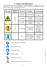
Страница 4: ...grams and signal words to the specific danger and the possible consequences Pictogram Damage injury to Keyword Definition Consequences Persons DANGER Immediate danger Death or severe injury WARNING Po...

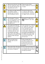
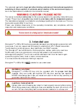
Страница 5: ...ructions they contain before they use the equipment and carefully follow them We further recommend that you have a qualified trainer show you how to use the product CAUTION The operating instructions...

Страница 6: ...ust always be complete and in a legible condition Any mode of operation which compromises the safety and or stability of the device is forbidden Repairs to the equipment may only be carried out by a t...

Страница 7: ...rimental to health if it is swallowed or its vapor is inhaled Direct contact with the skin must be avoided for the same reason Also when handling hydraulic fluid note that it can negatively affect bio...

Страница 8: ...d are to be implemented in addition to the instruction manual WARNING CAUTION PLEASE NOTE The device is intended exclusively for the purpose stated in the operating instructions see chapter Proper Use...

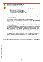
Страница 9: ...losive environment the following must be excluded that the device could trigger an explosion that working with the device could trigger an explosion e g sparks may result from cutting an object The re...

Страница 10: ...required hydraulic pressure takes place within the body of the device A rechargeable battery serves as drive and energy source The accumulator battery can be inserted into the opening provided in the...

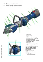
Страница 11: ...ry 4 Release button for battery 5 Handle rotates 360 6 Locking bolt pull up to unlock 7 Ventilation slots 8 Tool tips combination snap on tips 9 Blade arms 10 Pivot bolt with secured nut 11a Front pla...

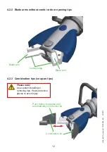
Страница 12: ...ut combi or door opening tips Blade arm Cutting edge Blade arm 4 2 3 Combination tips snap on tips Combination tip Push button to release and automatically lock the tool tip Please note Use caution in...

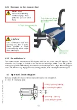
Страница 13: ...p 4 2 5 Rotatable handle The handle can be rotated about 360 degrees with four set points every 90 degrees This allows for easy change of position of the tool for the best angle attack To do this pull...

Страница 14: ...nitial operation the battery of the rescue device must be fully loaded using the external charger Procedure 1 Fully press back the red release button and pull the battery carefully out of the battery...

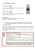
Страница 15: ...hored to ensure that there is no risk of sliding or shifting Worldwide safety guidelines pertaining to the specific country must be observed and complied with WARNING CAUTION PLEASE NOTE The StrongArm...

Страница 16: ...nclosed persons must be protected The following are to be worn when working with the rescue equipment protective clothing safety helmet with visor or protective goggles protective gloves safety shoes...

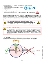
Страница 17: ...de tips Einheit mm in e100 le100 2 0 08 Higher cutting capacities can be achieved by cutting as close as possible to the blade s pivot point RIGHT WRONG 6 3 Spreading Use the front of the tips only to...

Страница 18: ...gap not suitable for spreading Tips get a safe grip Work with the tips only Do not damage the tool arms Illustration of the spreader tips as an example Every effort should be made to fully engage the...

Страница 19: ...nge plates and at each locking bolt if required 6 4 2 Procedure When applying the unit the claws must be pressed or beaten into the door crack as hard and deep as possible refer to application example...

Страница 20: ...clothing helmet with visor or goggles protective gloves Application example office door Application example steel door WARNING CAUTION ATTENTION During operation of this rescue device parts of the obj...

Страница 21: ...AUTION ATTENTION The load to be lifted must be secured against slipping as prescribed in the respective applicable guidelines and regulations WARNING CAUTION ATTENTION Before dismantling the used equi...

Страница 22: ...ged before connecting it to a rescue device Release button 7 Accessories NOTE Indicator lights are the same as found on SCBA systems Self Contained Breathing Apparatus Symbols G G Y R The charge statu...

Страница 23: ...or the battery charger 7 3 Attachment strap The single point attachment strap will be placed on the tool before the pump housing and tool head are assembled It is the ONLY recommended way to carry thi...

Страница 24: ...sed until the tips are only a few millimeters apart This relieves the hydraulic and mechanical strain on the equipment Clean the device after each operation and grease all metal surfaces as well as al...

Страница 25: ...ng the safety or reliability of the unit an additional function check is to be carried out complying with the applicable national and international regulations for the maintenance intervals of rescue...

Страница 26: ...icks or deformations on the cutting surfaces Cutting surfaces fit on top of each other without making contact Bolts and retaining rings of the blade arms are in place and in good condition Illuminatio...

Страница 27: ...need to be replaced The removable filter cover is located on the outside at the rear housing where it is fixed with two screws Procedure 1 Unscrew the two attachment screws at the cover with a torx w...

Страница 28: ...amage the equipment ATTENTION Because LUKAS devices are designed for highest performance only components specified in the spare parts list for the appropriate equipment may be replaced Other component...

Страница 29: ...s proceeding in reverse order Reinstall attachment screws Attachment screw hex socket head Keyway Protective cover 10 2 1 Care instructions The outside of the device should be cleaned with a damp clot...

Страница 30: ...e upper part Then take off the upper part 3 Position the new handle and hold it while mounting the lower part with the attachment screws use medium strength thread lock e g LOXEAL 54 03 or Loctite 243...

Страница 31: ...both blade arm bolts and remove them 6 Remove blade arms and replace with new ones 7 Reassembly is carried out in reverse order Blade arm bolt Blade arm Retaining ring Pivot bolt Lock screw Lock nut...

Страница 32: ...battery Device doesn t perform at its given power Device defective Repair by an authorized dealer by personnel specially trained by LUKAS or by LUKAS itself Following release the star grip does not re...

Страница 33: ...rage Further information about your device is available directly from LUKAS Since all values are subject to tolerances minor differences may occur between the data on your equipment and the data in th...

Страница 34: ...f 34845 LSF spreading force according to NFPA kN 24 lbf 53 HSF spreading force according to NFPA kN 30 lbf 6744 Force spreading min kN 28 lbf 6295 Maximum spreading path mm 212 in 8 3 Mass net without...

Страница 35: ...including rechargeable battery Device type e100 le100 Idling measured at a distance of 1 m according to EN dB A Full load measured at a distance of 1 m according to EN dB A Idling measured at a distan...

Страница 36: ...36 e100_le100_manual_173100085_EN 07 2017 13 EC Declaration of Conformity...

Страница 37: ...ng as you hold it down 3 Tap down the right side of the paddle switch constant light Tap again to stop illumination 4 Tap down the right side of the paddle switch and immediately re press within 0 4 s...

Страница 38: ...tachment screws hex socket head Paddle switch Rail clamp tensioning bolt Accessory rail image as a sample Rail groove Rail key NOTE Pay also strict attention to the separate operating instructions for...

Страница 39: ...ipment with your household waste According to the European Directive 2002 96 EC governing electrical and electronic waste and their application in national legislation old electrical equipment must be...

Страница 40: ...ging materials and removed items Subject to change LUKAS Hydraulik GmbH A Unit of IDEX Corporation Weinstrasse 39 D 91058 Erlangen Tel 49 0 91 31 698 0 Fax 49 0 91 31 698 394 E mail lukas info idexcor...

Отзывы: