Configuring the OC12-ATM Trunk Module
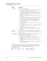
Monitoring APS redundancy
Stinger OC12-ATM Trunk Module Guide
29
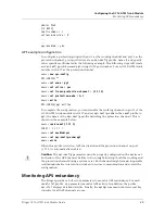
admin>
list
[in BASE]
shelf-number = 1
software-version = 9
...
...
aps-enabled = yes
APS example configuration
To configure a protection group with port 1 as the working channel and port 2 as the
protection channel, you must first create an
aps-config
profile, name it, and specify
other specifics as illustrated in the following example. The following steps will create
an
aps-config
profile named
pg1
, using OC12 port number 2 of an OC12-ATM trunk
module in slot 17 as the protection channel.
admin>
new aps-config
APS-CONFIG/””
admin>
set name = pg1
admin>
set active = yes
admin>
set linear-protection-channel = {1 17 2}
admin>
set protection-mode = 1+1
admin>
write
APS-CONFIG/pg1 written
To complete the configuration, you must enable the working channel on port 1 of the
OC12-ATM trunk module in slot 17 and set
aps-config-name
in the
sonet
profile to
pg1
(the name of the
aps-config
profile describing the protection channel). This is
shown in the example below.
admin>
read sonet {1 17 1}
SONET { 1 17 1 }
admin>
set enabled=yes
admin>
set aps-config-name=pg1
admin>
write
When this profile is written, APS is activated and the protection channel on port
{1 17 2} is automatically enabled.
!
Caution
The
aps-config
parameters must be properly configured on the devices at
both ends of the APS channel. Failure to do so might interrupt both the working and
the protection channel during a system reset. Both channels might remain inoperable
until administrative intervention is taken to restore communication and correct the
configuration.
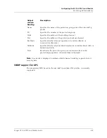
Monitoring APS redundancy
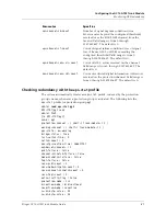
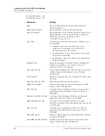
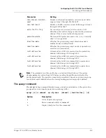
The Stinger provides a full set of parameters to monitor APS redundancy. For each
sonet-stat
profile, six parameters monitor APS activity. In addition, the profile
aps-stat
displays detailed statistics. Finally, the
apsmgr
command shows several key
statistics for all APS channels at once.


