Lucent Technologies Lineage
®
2000 100A Ferroresonant Rectifier J85503A-1
Issue 6 October 1998
Product Description 2 - 5
the rectifier meets all specified operating characteristics when
subjected to electric fields up to 10 volts per meter over a
frequency range of 20 to 1000 MHz.
Circuit Modules
The rectifier's signal processing and control circuitry are located
on replaceable circuit modules or packs. Circuit modules are
plug-in boards that can be ordered. All of the circuit modules are
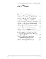
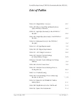
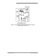
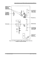
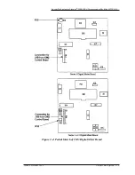
accessible by opening the rectifier's front panel door. Figure 2-1
shows the location of the circuit modules and other features of
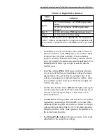
the rectifier. Figures 2-2, 2-3, and 2-4 show the CM1, CM2, and
CM3 board layouts, respectively. A description of each module
follows.
•
The CM1 circuit module (ED-83159-30 Group 1, A)
contains circuitry common to several rectifiers in the
Lineage
®
2000 rectifier family. The factory provides the
options required for each application by removing certain
wire straps and resistors from the CM1 board. The factory
modification of CM1 is complete when the board is
installed in the rectifier. However, ordered spare or
replacement CM1 boards have not been modified. The
customer must make this modification. See Section 8 for
information on parts to be removed and retained.
•
The CM2 control circuit module (208A) contains the
following circuits:
Local power supplies
Feedback regulator
Walk-in feature
Backup high voltage shutdown
Rectifier portion of external selective high voltage
shutdown
Remote shutdown
Manual on/off relay
Phase monitor
Restart feature
Unbalance shutdown
Fuse alarm
Electronic current limit
Output current isolation circuit
•
The CM3 circuit module (207A) controls the digital
Output meter on the rectifier control panel. The meter
displays the rectifier's output current, voltage, or the plant

