background image

system-electronics.it

USER MANUAL

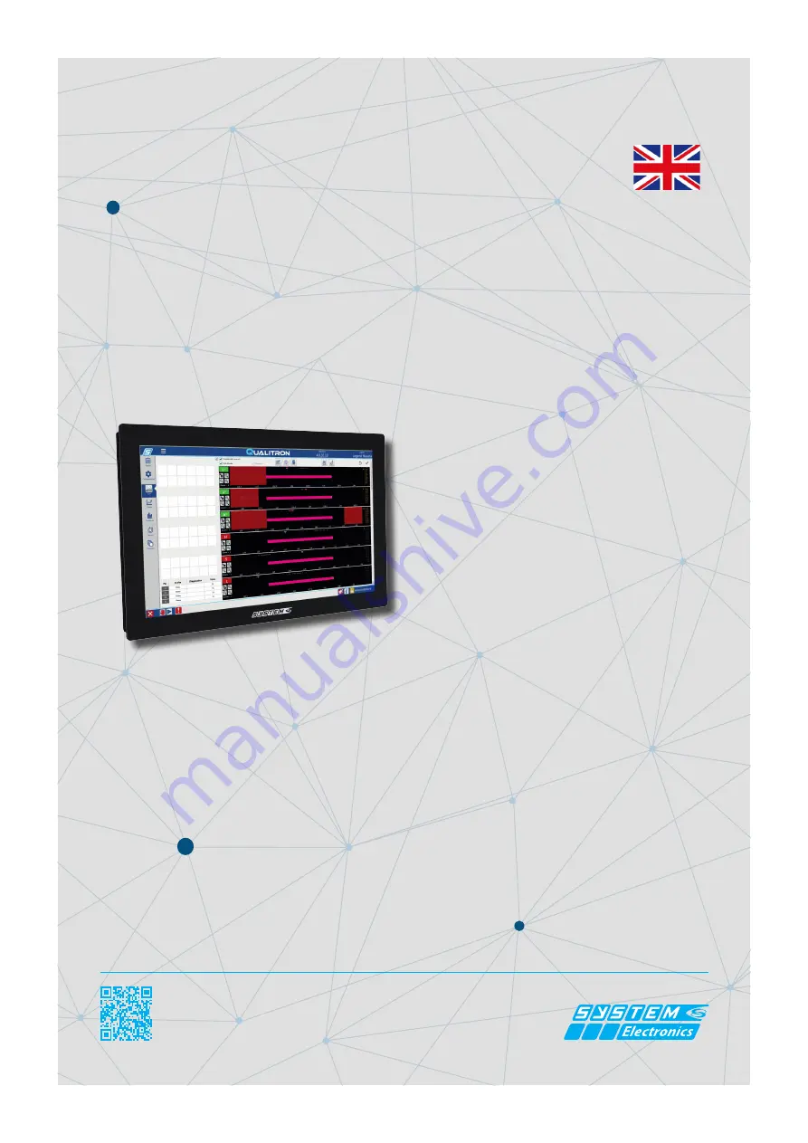
COPILOT 15.6’’

INDUSTRIAL PC

Order Code: : 

2E00xxxx*

Date:

 11

/2020

 - Rev: 

1.2

* The PC order code is specifi c to each specifi c confi guration defi ned by the customer.

Summary

1.

 General characteristics.........................................

3

2.

 Technical specifi cations..................................................

3

3.

Installation...............................................

3


3 .1

  P o w e r   c o n n e c t i o n . . . . . . . . . . . . . . . . . . . . . .

3


3. 2

 Connec tors layout ........................

3

4.

  Description and operation.........................................

4


4.1


 Hanging version installation (VESA100) ..........4


4.2

 Panel Mouthing........................................

4


4.3

 Option for foot mounting...................

5

5.

 Touch screen: operation and calibration........

6

 5.1

 Calibration of the touch screen.................................

7

 5.2


The default touch sett ings 

........................................

7

  5.3

 T

ouch screen-cleaning.

.......................................

8

6.


Adjusting the brightness of the display..............

8

7.

 Connectors available..........................................

9


7.1

 Ethernet RJ45...............................................

10


7.2

 USB....................................................................

10 

 7.3

 Power supply 24V........................................

10 

8.


Waste Electrical and Electronic Equipment Di-

rective (WEEE) and Restriction of Haz-

a r d o u s   S u b s t a n c e s   D i r e c t i ve   ( R O H S )


10

Содержание COPILOT Monitor 15.6"

Страница 1: ... layout 3 4 Description and operation 4 4 1 Hanging version installation VESA100 4 4 2 Panel Mouthing 4 4 3 Option for foot mounting 5 5 Touch screen operation and calibration 6 5 1 Calibration of the touch screen 7 5 2 The default touch settings 7 5 3 Touch screen cleaning 8 6 Adjusting the brightness of the display 8 7 Connectors available 9 7 1 Ethernet RJ45 10 7 2 USB 10 7 3 Power supply 24V 1...

Страница 2: ...system group it This product meets the EMC protection re quirements of Directive 2014 30 EC ex 89 336 EEC and subsequent amend ments SYSTEM Ceramics S p A Div Electronics reserves the right to make changes of any kind to the technical specifications at any time and without notice The in formation contained in this documentation is believed to be correct and reliable The reproduction even if partia...

Страница 3: ...bedded 7 Windows CE 7 0 Windows 8 1 64bit other on request Expansion slot 1 x miniPCIe LCD Size model 15 6 TFT Color LCD Max resolution 1920 x 1080 FullHD Touch Screen PCAP 10 tocchi Brightness 400 cd m2 Field angle 85 H 85 V Storage capacity HDD SATA up to 1TB 2 5 SSD Up to 256GB Input Output LAN 2 Eth 10 100 1000 Serial Doors 2 x RS232 RS422 RS485 optional PS2 Door Keyboard Mouse USB Up to 8 x U...

Страница 4: ...ted to the Co pilot 15 6 on the fixing arm making sure that they protrude for about 20cm beyond the fixing point of the arm itself cables that will be connected on the back of the PC itself Typically all connecting cables are connected from the bottom side of the Copilot 15 6 Place the Copilot 15 6 on the VESA arm It is possible to fix the Copilot 15 6 to the arm using the M4 screws supplied In th...

Страница 5: ... 6 in the hole of the panel inserting the TOP side first Secure the Copilot using the adjustable side blocks without exerting an excessive tightening torque Wire the connection cables 4 3 Foot mounting option The accessory for ground mounting is available The foot can be fixed to the floor and allows the passage of cables inside the joint The support foot on the ground allows the Copilot 15 6 to r...

Страница 6: ...with gloves or in dirty environments to opti mization of touch precision up to natural gestures with Windows rotation movement and zoom with the hand The Copilot 15 6 is supplied already calibrated and equipped with a setting that typically covers all needs without penalizing any however there are commands to customize the behavior according to the specific application Figure 4 3 3 Removing the fi...

Страница 7: ...IBRATE button To test the touch screen calibration touch the crosses with your finger each time they appear on the screen Click anywhere on the screen to return to the last ca libration Press ESC to exit Do not change the orientation of the monitor before completing the calibration process 5 2 Default settings of the touch parameters To set the factory configurations again select the RESET button ...

Страница 8: ...ave in contact with the surface for over 2 minutes After cleaning make sure you have removed all the residues present and carried out this operation only if necessary as for excessive pressure from part of the user may remove or damage the anti glare treatment 6 Adjusting the brightness of the display The Copilot 15 6 allows adjusting the brightness of the backlight using the communication of the ...

Страница 9: ...h different modules to adapt to the needs of the industrial world by replacing the lower closure it is possible to add buttons and keyboard or both 7 Connectors available The connectors can be customized according to the different application needs In addition to the power connector Ethernet USB and communication ports can be added Figure 6 2 Types of modules that can be ordered ...

Страница 10: ...parate waste collection of this equipment at the end of its life cycle is organised and managed by the manufacturer Any user who wishes to dispose of this equipment must therefore contact the manufacturer and follow the system adopted by the latter for the separate collection of the equipment at the end of its life cycle Adequate separate collection of the equipment which is subsequently recycled ...

Отзывы: