


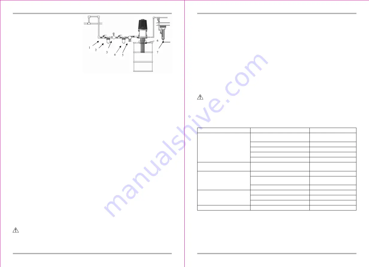
Fig.3: Oil supply system installation
4
3.2 Installation
3.2.1 Standard installation
1: cut-off valve
2: Filter
3: Regulator
4: Lubricator
5: Control valve
6: Locking adapter
7: Hose reel
The above installation is not the integrated oil supply system, just contact the manufacture or
distributor if you need. Installation for air circle.
3.2.1.1 Note: Do not hang any device at the air inlet, as there maybe dropping and damage.
3.2.1.2 Process
• Put the pump into lock adapter (Fig .3 Parts 6), Install to the trolley.
• Install cut-off valve (Fig3. Part1).
• Install filter (Fig 3. Part 2).
• Install regulator which control the speed and adjust the air pressure (Fig3. Part3).
• Install lubricator which with self-lubricate (Fig3. Part 4).
• Install control valve which control flux
,
When the speed is too fast, pump will be self-close
automatic to avoid pump be damaged (Fig.3 Parts5).
• Connect oil output.
3.3 Operation
3.3.1 Pressure Relief
3.3.1.1 Injury for skin
:
Before pressure relief by manual
,
Pump is under pressure
。
To reduce the
risk of serious injury from pressurized fluid, accidental spray from the valve, or splashing fluid, follow
this procedure whenever you
• Are instructed to relieve pressure
• Stop dispensing
• Check, clean, or service any system equipment
• Install or clean dispensing devices
3.3.1.2 Pressure Relief procedure
• Turn off the cut-off valve, shut off air
• Put the pump to the waste equipments, switch oil valve ,relief pressure
• Turn the air supply and oil fluid.
• Turn off the oil valve.
3.3.1.3. When occurs
:
• Problems on control valve, flexible hose, rigid tube or manual tip, auto tip.
• Pressure not relieve thoroughly according to above relief procedure.
• Pressure relieved very slowly until relieved thoroughly. Please clear obstruction of oil system.
3.3.2 Operation
3.3.2.1 Note: After initialize work, open the oil valve, pump start to work. Close the oil valve, pump
stop working.
3.3.2.2
WARNING:
Each device with different max working pressure. To reduce the risk of
exceed pressure. Make sure the max work pressure for each device. Rated pressure in the system
can not exceed the max pressure of any device. Or there will be burst, explosion, malfunction,
serious damage.
5
3.3.2.3 Remind: Pump can not operate with empty load. Or the speed will be very fast which will
self-damage.
If acceleration is too fast or running very slow, Should stop operation and check that if there is
enough oil in the barrel. If there is insufficient oil, change the trolley and initialize the whole system.
3.3.2.4 Startup
• If there is several pump in the whole system, please use control valve to dispatch the air.
• Open the main control valve.
• Open the oil valve which with effective grounding with the trolley. Keep the connecting of the
metal forboth oil valve and trolley. Open the cut-off valve, pump start to work. When the pump is
stable. Close theoil valve.
• If there are several pumps in the whole system, startup for each pump step by step with above
instruction.
• To get perfect result, set up the min air pressure for each device.
• Pump can not operate under empty load.
• Relief pressure before close the pump.
4 Trouble Shooting
WARNING:
To reduce the risk of serious injury whenever you are instructed to relieve pressure.
Do not remove silencer, or it may cause finger be injury.
4.1 Before check and maintain, pay more attention of the relieve of pressure.
4.2 Ordinary problems, reason and solution
Problem
Pump fails to operate
Continuous air exhaust
Erratic pump operation
Pump operates, but output low on
both strokes
Leakage from silencer
Solution
Cause
Inadequate air supply pressure or
restricted air lines
Closed or clogged dispensing valve
Clogged fluid lines, hoses, valves, etc
Damaged air motor
Exhausted fluid supply
Worn or damaged air motor gas-kit,
packing, seal, etc.
Exhausted fluid supply
Held open or worn intake valve or
piston packing
Hose damaged
Piston damaged
Seal O-ring damaged
Hose, valve or other device block
O-ring damaged
Increase air supply; clear
Open; clear
Clear
Service air motor
Refill and re-prime or flush
Service air motor
Refill and re-prime or flush
Clear; service
Change hose
Change piston
Change O-ring
Relieve pressure
Change O-ring


