


Digital Video Recorder User Manual
26
Rear Panel2
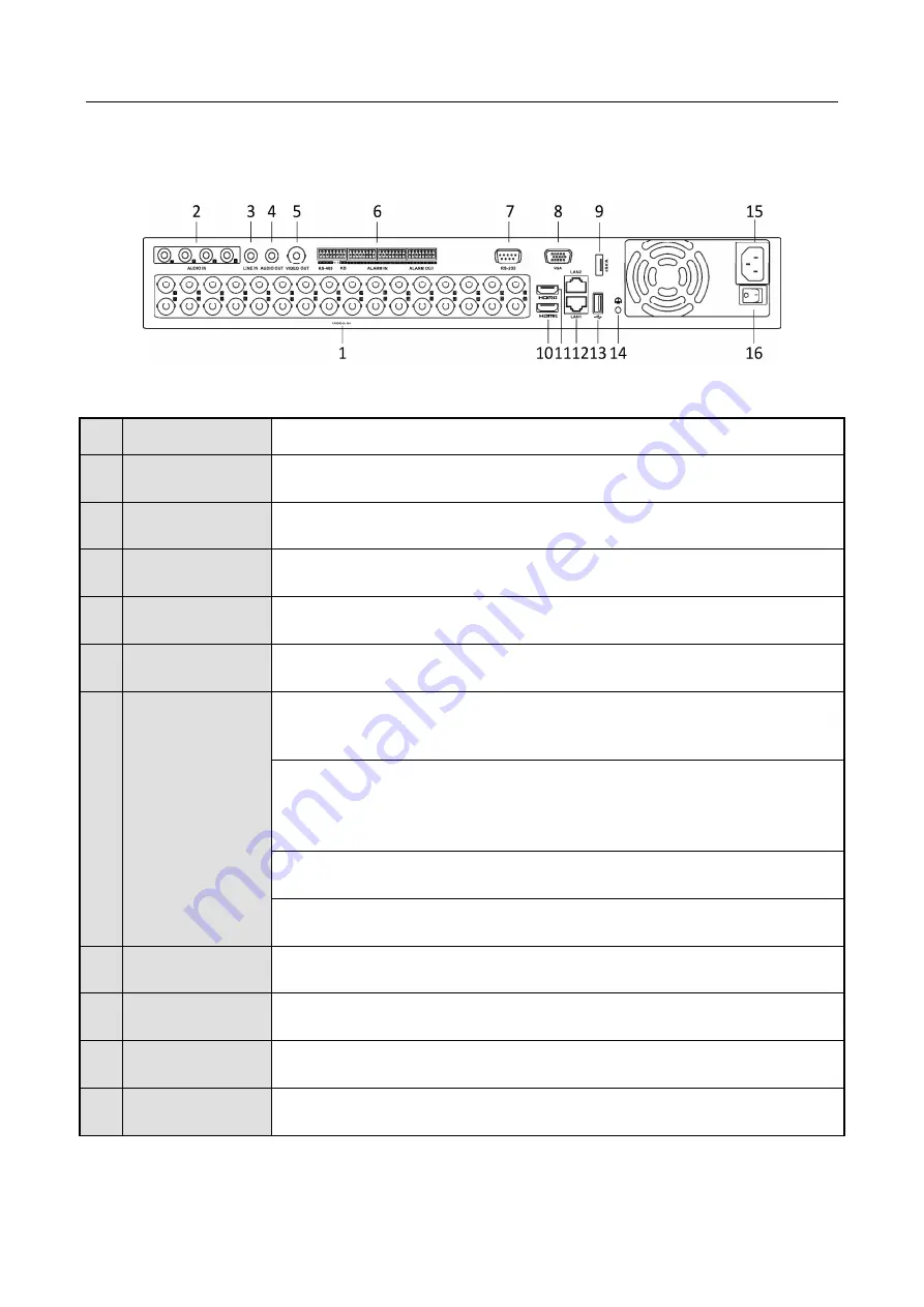
Figure 1-5
Rear Panel of LTD8432K-ST (with 32 Video Inputs)
No. Item
Description
1
VIDEO IN
BNC interface for Turbo HD and analog video input.
2
AUDIO IN
RCA connector.
3
LINE IN
BNC connector for audio input.
4
AUDIO OUT
RCA connector.
5
VIDEO OUT
BNC connector for video output.
6
RS-485 and
Alarm Interface
Connector for RS-485 devices. T+ and T- pins connect to R+ and R- pins of
PTZ receiver respectively.
D+, D- pin connects to Ta, Tb pin of controller. For cascading devices, the
first DVR’s D+, D- pin should be connected with the D+, D- pin of the next
DVR.
Connector for alarm input.
Connector for alarm output.
7
RS-232 Interface
Connector for RS-232 devices.
8
VGA Interface
VGA video output connector. Display local video output and menu.
9
eSATA
Connects external SATA HDD, CD/DVD-RW.
10
HDMI1 Interface
HDMI1 video output connector. Display local video output and menu.