background image

Lowrance | Link-5 VHF User Guide

18

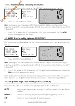
2-5-7 GPS Alert Options (ALERT) 

The GPS alert is usually set to ON (on) so that if the GPS navigation receiver is disconnected, 
the alarm sounds.

1. 

Select GPS/DATA, then SETTING.

2. 

Select GPS ALERT.

3. 

Select ON (on) or OFF (off ) as 

desired.

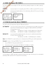
2-6 GPS Simulator (SIMULATOR)

The GPS Simulator is set to OFF whenever the radio is switched ON, or whenever real GPS 
data is available through the COM port. However, if you want to test it, turn it on. 

1.  Select GPS SIM, then select ON (on) or OFF (off ) as desired. 

Whenever the GPS Simulator is turned ON (on),  simulated 
Speed Over Ground (SOG), Course Over Ground (COG), and LL 
position appear on the screen. This data is updated automati-
cally during the simulation.

Important: It is not possible to send a DSC transmission when in Simulator mode.

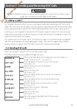
2-7 Reset to Factory Defaults (RESET)

Use this setting to return every setting to the factory defaults except all MMSI settings, entries 
in your buddy list and any edited channel names. 

1. 

Select  RESET. The radio asks for confirmation.

2. 

Select YES to reset the radio and return to the menu.

MENU SELECT
 RADIO SETU

 GPS SIM

RESET

RESET RADIO
ARE YOU SURE

YES

 NO

MENU SELECT
 DSC SETUP 

 RADIO SETUP

GPS SIM   

SETTING
 LL DISPLY 

 COG/SOG

GPS ALERT

GPS ALERT


ON

OFF


Draft 

- Final 

approval

Содержание Link-5

Страница 1: ...ENGLISH Link 5VHF User Guide lowrance com D r a f t F i n a l a p p r o v a l ...

Страница 2: ...nuals and the most current information on this product its operation and accessories visit our web site www lowrance com Important safety information Please read carefully before installation and use DANGER This is the safety alert symbol It is used to alert you to potential personal injury hazards Obey all safety messages that follow this symbol to avoid possible injury or death WARNING WARNING i...

Страница 3: ...et the Backlighting Level 15 2 4 2 Set the Contrast Level 15 2 5 GPS Data and Time GPS DATA 15 2 5 1 Manually Enter Position and UTC Time MANUAL 15 2 5 2 Local Time TIME OFFSET 16 2 5 3 Time Format Options TIME FORMAT 16 2 5 4 Time Display Options TIME DISPLAY 17 2 5 5 Position Display Options LL display 17 2 5 6 Course Speed Display Options COG SOG 17 2 5 7 GPS Alert Options ALERT 18 2 6 GPS Simu...

Страница 4: ...0 Set the inactivity timer TIMEOUT 28 Section 5 Sending and Receiving DSC Calls 29 5 1 What is DSC 29 5 2 Sending DSC calls 29 5 2 1 Make a Routine Call INDIVIDUAL 30 5 2 2 Retrying a Routine Call 31 5 2 3 Acknowledgement of an Individual Incoming Call INDIV 31 5 2 4 Recall the Most Recent Incoming Call LAST CALL 32 5 2 5 Call a Group GROUP 32 5 2 6 Call All Ships ALL SHIPS 32 5 2 7 Call using the...

Страница 5: ...nter Your User MMSI 49 The Completed Installation 50 Appendix A Technical Specifications 51 Appendix B Troubleshooting 53 Appendix C US ROW VHF Marine Channel Charts 54 C 1 International Channel Chart 54 Special Notes on International Channel Usage 55 C 2 USA Channel Chart 56 Special Notes on USA Channel Usage 57 C 3 CANADA Channel Chart 58 Special Notes on Canada Channel Usage 59 C 4 US Canada WE...

Страница 6: ...International including weather channels where available model dependant Special CH16 9 key for quick access to the priority international distress channel Special 3CH key to select your three favourite channels Dedicated Wx Weather key PSCAN similar to dual watch facility DSC Digital Select Calling capability that meets Global DSC Class D Standards Separate CH70 receiver included built in DISTRES...

Страница 7: ... Scroll rotate the Rotary knob or use keys on the hand mic to scroll up and down the menu until the cursor is positioned at the desired option Press ENT press the Push To Select to display that option 3 Make any entries or changes as explained in the following section 4 Press ENT to confirm changes Otherwise press EXIT to keep the original entry 5 Press EXIT to backup one screen this key is equiva...

Страница 8: ...annel selected USA INT CAN Selected channel bank for VHF radio operations and regulations DSC Auto channel switch function is disabled OFF see section 4 8 B A Channel suffix if applicable CH1 CH2 CH3 Shows which of the 3 favourite channels if any are selected Otherwise blank ATIS EU models only must be enabled when in European inland waterways A typical display The latitude and longitude of the ve...

Страница 9: ...vity is reduced Either turn SQL slowly clockwise or use the LOCAL setting See section 2 3 16 9 Priority Channel Also on the handset mic Press to cancel all other modes and to tune into the priority channel Press again to return to your original channel The default Priority Channel is CH16 For US models To make Channel 09 the priority channel hold down 16 9 until a beep sounds and 09 is displayed W...

Страница 10: ...d 3CH to store it in the CH1 location Repeat the procedure to store two more favourite channels in the CH2 and CH3 locations respectively If you try and add another favourite channel it will overwrite the existing CH3 CH1 and CH2 remain unless you delete them To delete a favourite channel select that channel then hold down 3CH until the CH1 CH2 or CH3 symbol disappears off the LCD SCAN Scan Press ...

Страница 11: ... The current channel is shown on the LCD in BIG digits and an A or B designator suffix if applicable in small letters below the channel number See appendix C for a listing of channel frequencies Push to activate the ENT function You can also use the rotary knob for alphanumeric entry Turn to step through alphanumeric characters one at a time then push to confirm each selection If you make an error...

Страница 12: ... Setup Menu See Section 3 Turn the GPS Simulator on off See Section 2 6 Reset factory settings See Section 2 7 Model dependant Sections 1 3 and 1 4 explain how to navigate around the menu and enter save and change data BUDDY LIST LOCAL DIST BACKLIGHT CONTRAST GPS DATA DSC SETUP RADIO SETUP GPS SIM RESET USER MMSI GROUP SETUP ATIS MMSI ATIS FUNC INDIV REPLY DSC FUNC LL REPLY AUTO SWITCH TEST REPLY ...

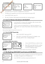
Страница 13: ...on your BUDDY LIST Section 5 explains how to call a buddy 2 2 1 Add an Entry 1 Select BUDDY LIST The cursor is at MANUAL NEW Press ENT 2 Enter the buddy name one character at a time this may be alphanumeric then press ENT repeatedly until the cursor moves to the MMSI entry line 3 Enter the MMSI associated with that buddy name this must be numeric then press ENT If the MMSI is for a Coast Station e...

Страница 14: ... DIST then select DIST 2 Press ENT to activate the DIST setting This disables local sensitivity and the menu is displayed again 2 3 2 Set LOCAL Sensitivity 1 Select LOCAL DIST then scroll to LOCAL 2 Press ENT to activate the LOCAL setting This disables distance sensitivity and the menu is displayed again LOCAL is displayed on the LCD as a reminder that local sensitivity is selected 2 4 Backlightin...

Страница 15: ...y the vessel position and the local time manually using the GPS DATA option This information is important because it will be used if a DSC distress call is transmitted You can also select GPS Alert and GPS Simulator options 2 5 1 Manually Enter Position and UTC Time MANUAL Note that this function is available only if an operational GPS receiver is not connected 1 Select GPS DATA then MANUAL 2 Ente...

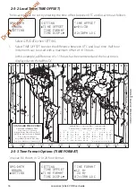
Страница 16: ... R V U T S R Q P T S A A Z B C Z A B B B C S S S R H I K K M M H H H I K F G E D E C C D G H E F H I G C E K L Z Z P N 0 30 E 60 E 90 E 120 E 150 E 30 W 60 W 90 W 120 W 150 W 180 180 L Z N O O Z Z Z C D D E F E F K L L L M M Q O Q A S U W V A Y M L M Y P K H M X X W W X M W M M M M L M M K I D F G I I I K L L Z International Date Line International Date Line WORLD MAP OF TIME ZONES R C B B A P R I...

Страница 17: ...ered the vessel position manually as described in the previous section the vessel position is always shown on the screen with the suffix M However if the time is being updated through a GPS navigation receiver you can switch the vessel position display on the screen on or off as follows 1 Select GPS DATA then SETTING 2 Select LL DISPLAY 3 Select ON on or OFF off as desired In this example OFF has ...

Страница 18: ...ulator is turned ON on simulated Speed Over Ground SOG Course Over Ground COG and LL position appear on the screen This data is updated automati cally during the simulation Important It is not possible to send a DSC transmission when in Simulator mode 2 7 Reset to Factory Defaults RESET Use this setting to return every setting to the factory defaults except all MMSI settings entries in your buddy ...

Страница 19: ... Appendix C Edit or delete channel names See Section 3 3 Selects if the WX Alert scanning mode is ON on or OFF off See section 3 7 Selects Priority Channel operation with Dual or Tri watch scanning See section 3 6 Switch ON OFF on off the radio s internal speakers See section 3 5 Select NMEA protocol for communications between the VHF radio and any other instruments See section 3 8 Set the volume ...

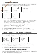
Страница 20: ... confirm the new channel name tag or the deletion then press EXIT to return to the menu 3 4 RING BEEP Volume RING VOLUME and KEY BEEP Set the volume level of the incoming signal beeps RING VOLUME and or the error and warn ing beeps KEY BEEP to HIGH high or LOW low as follows 1 Select RADIO SETUP then RING VOLUME or BEEP VOLUME as appropriate 2 Select a HIGH or LOW volume It is possible to turn the...

Страница 21: ...IO SETUP then WX ALERT 2 Select ON on or OFF off then press ENT to enable the setting and return to the menu When a weather alert is broadcast the alarm will sound Press any key to hear the weather alert voice message 3 8 NMEA protocol COM PORT This radio uses NMEA 0183 protocol to receive GPS data from a compatible GPS unit The COM Port must be configured correctly before use The radio can be add...

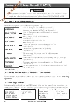
Страница 22: ...nctions can be used See below for instructions on how to Enter Your USER MMSI USER MMSI Enter or view your user MMSI See section 4 2 If you do not have a user MMSI see Appendix D Enter or change the name and or details of a group See section 4 3 Select the type of response to an LL polling request See section 4 7 Turn the DSC operation ON OFF on off See section 4 6 Choose an automatic or manual re...

Страница 23: ...intain Your Groups GROUP SETUP Use GROUP SETUP to create edit or delete 1 2 or 3 groups of frequently called people stored in alphanumeric order A group MMSI always starts with 0 4 3 1 Create a Group GROUP SETUP DSC SETUP USER MMSI GROUP SETUP INDIV REPL GROUP SETUP MANUAL NEW 000000000 GROUP NAME GROUP MMSI 0 FISHER1 012345678 STORE CANCEL 1 Select DSC SETUP then GROUP SETUP 2 If this is the firs...

Страница 24: ...TUP then GROUP SETUP The existing group names are displayed 2 Press or to scroll to the incorrect entry then press ENT 3 Select DELETE and press ENT The radio asks for confirmation 4 Press ENT to delete the group and return to the GROUP SETUP screen 4 4 Response to Individual Calls INDIV REPLY You can respond to incoming individual calls with an automatic response or with a manual response Note th...

Страница 25: ...s with the number 9 1 To enter or edit your ATIS MMSI 2 Select DSC SETUP then ATIS MMSI 3 If this is the first time that you are entering your ATIS MMSI a dashed line appears Enter your ATIS MMSI along the dashed line using the rotary knob as described in Section 1 4 The first number is always 9 Press ENT to confirm each correct entry and to move to the next digit If you make an error press until ...

Страница 26: ...DSC FUNC DSC FUNC ON OFF ATIS IS ON 1 Select DSC SETUP then DSC FUNC Note It is not possible to have both ATIS ON on and DSC ON on simultaneously If you want to activate DSC you must first switch ATIS off A note on the LCD will remind you if ATIS is already ON 2 Select ON to enable the DSC functionality ATIS if applicable must be turned off first The DSC annunciator appears on the screen There are...

Страница 27: ...n the current channel by pressing the EXIT button However automatic switching to a subsequent communications channel on receipt of a DSC call might in some cases disrupt important ongoing communications if the working channel changes without the operator knowing You can prevent the radio from automatically switching from the current working channel by setting the AUTO SWITCH feature to OFF If the ...

Страница 28: ...TRESS or DISTRESS Timeout options are DISTRESS NO TIMEOUT 5 MINS 10 MINS default is NO TIMEOUT NON DISTR NO TIMEOUT 10 MINS 15 MINS default is 15 MINS NON AUTO you can set the inactivity timer to exit any non automated procedure activity Timeout options are NO TIMEOUT 10 MINS 15 MINS default is 10 MINS Note If NO TIMEOUT is selected then you must press the EXIT key to exit the procedure Example to...

Страница 29: ...Sending DSC calls Press CALL to show the types of DSC call that can be made The following options are available through CALL key WARNING A valid USER MMSI must be entered into this radio before these DSC functions can be used See 4 2 Enter Your USER MMSI USER MMSI Make a individual call or acknowledgement to a new caller or a buddy See Section 5 2 1 5 2 2 and 5 2 3 Make a call to one of your three...

Страница 30: ... press ENT to select MANUAL NEW to call a person that is not in your buddy list otherwise select the name of your buddy Press ENT If you selected MANUAL NEW you need to enter the user MMSI and then press ENT Note If the MMSI is for a Coast Station enter the 7 digits then press ENT twice 3 Select the working channel and press ENT Note Duplex channels cannot usually be called and are automatically e...

Страница 31: ...CH knob to stop the alarm 2 Push button or rotate the CH knob to scroll any further information about the call 123456789 CH12 REQUEST 12 45 UTC 00 03 ROUTINE FROM 123456789 CH12 REQUEST 00 02 INDIVIDUAL ROUTINE FROM 123456789 00 01 CH12 REQUEST 12 45 UTC ENT OPTION 00 04 OPTION ACK CHANGE CHAN 12 45 UTC ENT OPTION KEY SILENCE 00 05 ENT OPTION KEY SILENCE EXIT ESC 00 06 3 Press ENT for options on h...

Страница 32: ...nd asks for confirmation to send the call SEND Press ENT to send the call and continue as explained in Section 5 2 1 5 2 5 Call a Group GROUP RD GROUP 055554444 ROUTINE SET CHANNEL SELECT GROUP RD GROUP GROUP 2 GROUP 3 DSC CALL INDIVIDUAL LAST CALL GROUP RD GROUP 055554444 ROUTINE SEND 1 Press CALL to enter DSC mode then select GROUP The radio displays the names of your groups you setup in section...

Страница 33: ...ng the Distress Log DISTR LOG DSC CALL ALL SHIPS CALL LOG DISTR LOG BOBBY D CALL BACK DELETE SAVE MMSI BOBBY D INDIVIDUAL ROUTINE SET CHANNEL 01 BOBBY D DISTRESS UNDESIG ENT OPTION The Distress Log contains the Distress Log data for the last 20 re layed Distress Calls so that you can call any of them quickly Always try to make voice contact on CH16 first as follows 1 Press CALL to enter DSC mode t...

Страница 34: ... 3 You now have three options CALL BACK to CALL the contact DELETE to delete the entry from the call log select YES to confirm SAVE MMSI to save the MMSI You will be asked to add a name for the contact 5 2 10 Request the LL Position of a Buddy LL REQUEST SAM LL REQUEST SEND LL REQUEST SAM TOM BUDDY 3 DSC CALL DIST LOG SENT CALL LL REQUEST SAM LL REQUEST CALLING 1 Press CALL to enter DSC mode then ...

Страница 35: ... WAITING ACK If the call is acknowledged DSC TEST ACK notification is displayed 6 If there is no reply after 30 seconds the radio asks you if you want to retry 5 2 11 2 Receiving an incoming DSC TEST call reply DSC TEST ACK 1 When you receive notification of a DSC TEST reply press any key to cancel the alert 2 If the radio recognizes the user MMSI as one of your buddies the buddy s name is display...

Страница 36: ...ceiving DSC Calls Several types of DSC calls can be received from vessels within range at various priority levels DISTRESS See Section 6 ALL SHIPS Urgency Safety Routine or Distress priority see Section 5 3 1 INDIVIDUAL Urgency Safety Routine or Distress priority see Section 5 3 2 GROUP Routine priority only see Section 5 3 3 GEOGRAPHIC Routine priority only see Section 5 3 4 POLLED POSITION Routi...

Страница 37: ...0 05 AUTO SWITCH CH14 IN 10S 10 12 UTC 00 04 However If AUTO SWITCH OFF then AUTO SW OFF will be displayed and manual channel change is required TOM AUTO SW OFF CH14 REQUEST 00 18 SAFETY FROM TOM AUTO SW OFF 00 15 ALL SHIP SAFETY FROM TOM 00 12 10 12 UTC ENT ACCEPT KEY SILENCE 00 25 CH14 REQUEST 10 12 UTC ENT ACCEPT 00 23 AUTO SW OFF CH14 REQUEST 10 12 UTC 00 20 3 No acknowledgement is needed Pres...

Страница 38: ...ve notification of a GROUP call press any key to cancel the alert The priority level is always routine and the group is identified on the screen The group will be one of the three groups of frequently called people that you set up earlier see Section 4 3 2 Press ENT to switch to the designated channel immediately or press EXIT to return to the current working channel Note The radio will automatica...

Страница 39: ...ss EXIT to return to the current working channel TOM CH13 REQUEST 10 11 UTC 00 25 CALL FROM TOM CH13 REQUEST 00 22 GEOGRAPHICAL CALL FROM TOM 00 12 10 11 UTC ENT ACCEPT KEY SILENCE 00 32 CH13 REQUEST 10 11 UTC ENT ACCEPT 00 28 3 Monitor the working channel for an announcement from the calling vessel 5 3 5 Receiving a Polled Position Call POSITION When you receive GPS position data from a buddy in ...

Страница 40: ...s 3 TO SEND A DISTRESS CALL with Distress type 4 Press and release the DISTRESS key to display the following categories Use the CH knob to scroll to the category that describes your situation UNDESIGNATED Undesignated FIRE Fire FLOODING Flooding COLLISION Collision GROUNDING Grounding LISTING Listing SINKING Sinking ADRIFT Adrift ABANDONING Abandoning PIRACY Piracy OVER BOARD Over Board 5 Hold dow...

Страница 41: ...N PAUSE CANCEL RESEND 03 20 SEND CANCEL YES NO RESEND 03 20 DISTR CANCEL SENDING DISTR CANCEL SENT PTT REASON DISTR CANCEL COMPLETED EXIT ESC 8 After a DISTRESS ACK is received rotate the CH knob to silence the alarm then use the PTT microphone to report your situation 9 The following information if available is contained in the DIstress Call Nature Of Distress if available Position information Th...

Страница 42: ...is provides the position of the distressed vessel to within 20 m 60 ft 6 3 Distress Acknowledgement DISTRESS ACK or Relay An alert sounds when a Distress Relay DISTRESS RELAY is received Press any key to cancel the alert DISTRESS ACK FROM 123456789 00 01 ACK FROM 123456789 82 50 178N 00 02 123456789 82 50 178N 024 45 342W 00 03 Try to make voice contact with the calling vessel Maintain a listening...

Страница 43: ...NT to ACK the call 4 Or press EXIT to return to standby The call data is stored in the Call Log see Section 5 2 7 900000000 FLOODING 55 29 975 N 00 02 RELAY 900000000 FLOODING 00 01 INDIV DISTR RELAY 00 00 FLOODING 55 29 975 N 012 18 559 E 00 03 02 43UTC AUTO SWITCH CH16 IN 10S 00 06 012 18 559 E 02 43UTC AUTO SWITCH 00 05 55 29 975 N 012 18 559 E 02 43UTC 00 04 AUTO SWITCH CH16 IN 10S KEY SILENCE...

Страница 44: ...not be adjusted Location Requirements Please check these before doing any cutting or drilling Whichever installation method you choose ensure that the chosen location Is at least 3 1 m from the antenna Allows easy connection to at least a 10 Amp fused 13 6 V DC electrical source and the antenna Is at least 1 5 45 cm from the compass to avoid creating magnetic deviation of the compass during radio ...

Страница 45: ...hone bulkhead mount 13 Two plain washers for the microphone bulkhead mount 14 Two nuts for the microphone bulkhead mount 15 Four M5x32 screws for recessed instal lation 16 Four nuts for the recessed installation Not pictured Installation template Warranty card DSC Warning label sticker This Operation and Installation manual One 7 Amp spare fuse in case of ac cidental reverse of battery polarity Ba...

Страница 46: ... set of four flat screws spring washers plain washers and nuts to attach the mounting gimbal to the location site 4 Slide the radio into the mounting gimbal 5 Insert the two mounting knobs through the holes and tighten them sufficiently to hold the radio at the desired viewing angle Change the Viewing Angle The viewing angle on the gimbal mount has a 20º tilt range To change the current viewing an...

Страница 47: ...the bulkhead Install the Microphone Bulkhead Mount 1 Hold the microphone bulkhead mount at the chosen location and use a soft pencil to mark the screw hole positions on the mounting surface Ensure that the microphone curly cable will comfortably reach this location BEFORE you drill 2 Drill the two pilot screw holes where marked 3 Use a short length Philips screwdriver and the set of two flat screw...

Страница 48: ...al Speaker connector Connect to an external speaker BEFORE powering on the radio Use a 4 Ohm 4 Watt external speaker White wire to speaker Bare wire to speaker NOTE Ensure wires are electrically insulated if not used ANT A radio antenna is not supplied A suitable radio antenna must be mounted and connected before operating this radio Consult your dealer for advice if necessary GND A ground connect...

Страница 49: ...I begins with 00 followed by 7 numeric digits You just need to add the 7 digits and the radio will add the beginning 00 for you Enter Your User MMSI See section 4 2 Enter Your USER MMSI USER MMSI CAUTION You can t make any DSC transmissions until you ve obtained a user MMSI and entered it into your radio Wiring for GPS COM connector Pin Wire Function Notes 1 Red No connection Not used 2 Orange OUT...

Страница 50: ...tallation 12 V DC Battery VHF Antenna GPS product Antenna cable External speaker Black power cable Fuse on Red power cable External speaker cable Link 5 Base unit with speaker microphone GPS COM NMEA connection cable D r a f t F i n a l a p p r o v a l ...

Страница 51: ... Antenna connector SO 239 50 ohm Temperature Range 20ºC to 55ºC 5ºF to 130ºF Waterproof JIS 7 Dimensions 161 W x 75 H x 147 D mm without bracket Weight 1 29 kg 2 8 lbs without microphone Frequency stability 10 ppm Frequency control PLL GPS NMEA input Yes Comm port 4800 baud NMEA 0183 DSC Yes CLASS D Global separate CH70 receiver built in GPS NMEA input Yes GPS data sentences can be received RMC GG...

Страница 52: ...pen short circuit of antenna Max Frequency deviation 5 kHz Spurious harmonics better than 0 25 µ W Modulation distortion Less than 4 1 kHz for a 3 kHz deviation RECEIVER Frequency 156 025 163 275 MHz 12dB SINAD sensitivity 0 25 uV distant 0 8 uV local 20db SINAD sensitivity 0 35 uV Adjacent CH selectivity more than 70 db Spurious response more than 70 db Intermodulation Rejection ratio more than 6...

Страница 53: ...engine b Add a noise suppressor to the power cable c Use resistive spark plug wires and or use an alternator whine filter 4 No sound from the external speaker a Check that the external speaker cable is physically connected b Check the soldering of the external speaker cable 5 Transmissions are always on low power even when high HI power is selected The antenna may be faulty a Test the transceiver ...

Страница 54: ...ns Yes Yes VTS 12 156 600 156 600 S Port Operations Yes Yes PORT OPS VTS 13 156 650 156 650 S Inter ship Navigation Safety bridge to bridge Yes No BRIDGE COM 14 156 700 156 700 S Port Operations Yes Yes PORT OPS VTS 15 156 750 156 750 S Port Operations Yes Yes PORT OPS 1 1W only 16 156 800 156 800 S International Distress Safety and Calling Yes Yes DISTRESS 17 156 850 156 850 S State Controlled Ye...

Страница 55: ... bridge Yes No BRIDGE COM 68 156 425 156 425 S Inter ship Yes No SHIP SHIP 69 156 475 156 475 S Port Operations Yes Yes PORT OPS 70 156 525 156 525 Digital Selective Calling DSC DSC 2 71 156 575 156 575 S Port Operations Yes Yes PORT OPS 72 156 625 156 625 S Inter ship Yes No SHIP SHIP 73 156 675 156 675 S Port Operations Yes Yes PORT OPS 74 156 725 156 725 S Port Operations Yes Yes PORT OPS 77 15...

Страница 56: ...lled Yes Yes SAR 1 1W only 18A 156 900 156 900 S Commercial Yes Yes COMMERCIAL 19A 156 950 156 950 S Commercial Yes Yes COMMERCIAL 20 157 000 161 600 D Port Operations Canadian Coast Guard No Yes PORT OPS 20A 157 000 157 000 S Port Operations Yes Yes PORT OPS 21A 157 050 157 050 S U S Government Canadian Coast Guard Yes Yes UNAUTHORIZED 4 22A 157 100 157 100 S Coast Guard Liaison Yes Yes COAST GUA...

Страница 57: ...creational Yes Yes PLEASURE 72 156 625 156 625 S Boat Operations Recreational Yes No SHIP SHIP 73 156 675 156 675 S Port Operations Yes Yes PORT OPS 74 156 725 156 725 S Port Operations Yes Yes PORT OPS 77 156 875 156 875 S Port Operations Yes Yes PORT OPS 1 1W only 78A 156 925 156 925 S Boat Operations Recreational Yes No SHIP SHIP 79A 156 975 156 975 S Commercial Yes Yes COMMERCIAL 80A 157 025 1...

Страница 58: ...TS 15 156 750 156 750 S Commercial Yes Yes COMMERCIAL 1 1W only 16 156 800 156 800 S International Distress Safety and Calling Yes Yes DISTRESS 17 156 850 156 850 S State Controlled Yes Yes SAR 1 1W only 18A 156 900 156 900 S Commercial Yes Yes COMMERCIAL 19A 156 950 156 950 S Canadian Coast Guard Yes Yes CANADIAN CG 20 157 000 161 600 D Canadian Coast Guard No Yes CANADIAN CG 1 1W only 21 157 050...

Страница 59: ...1 156 575 156 575 S Boat Operations Recreational Yes Yes PLEASURE 72 156 625 156 625 S Inter ship Yes No SHIP SHIP 73 156 675 156 675 S Commercial Fishing Only Yes Yes COMMERCIAL 74 156 725 156 725 S Commercial Fishing Only Yes Yes COMMERCIAL 77 156 875 156 875 S Port Operations Yes Yes PORT OPS 1 1W only 78A 156 925 156 925 S Boat Operations Recreational Yes No SHIP SHIP 79A 156 975 156 975 S Com...

Страница 60: ...radios Note The CANADA mode is not legal to use in U S waters KEY S Simplex operating channel D Duplex operating channel C 4 US Canada WEATHER Channels CH RX MHz TRAFFIC TYPE NAME REMARK WX01 162 550 NOAAWeather Channel NOAAWX RX only WX02 162 400 NOAAWeather Channel NOAAWX RX only WX03 162 475 NOAAWeather Channel NOAAWX RX only WX04 162 425 NOAAWeather Channel NOAAWX RX only WX05 162 450 NOAAWeat...

Страница 61: ... Yes DISTRESS 17 156 850 156 850 S Inter ship Yes Yes PORT OPS 1 1W only 18 156 900 161 500 D Public Correspondence Port Op No Yes PHONE PORTOP 19 156 950 161 550 D Public Correspondence Port Op No Yes PHONE PORTOP 20 157 000 161 600 D Public Correspondence Port Op No Yes PHONE PORTOP 21 157 050 161 650 D Public Correspondence Port Op No Yes PHONE PORTOP 22 157 100 161 700 D Public Correspondence ...

Страница 62: ...DSC DSC 2 71 156 575 156 575 S Port Operations Yes Yes PORT OPS 72 156 625 156 625 S Inter ship Yes No SHIP SHIP 73 156 675 156 675 S Inter ship Yes Yes SHIP SHIP 74 156 725 156 725 S Port Operations Yes Yes PORT OPS 75 156 775 156 775 S Port Operations Yes Yes PORT OPS 1 1W only 76 156 825 156 825 S Port Operations Yes Yes PORT OPS 1 1W only 77 156 875 156 875 S Inter ship Yes No SHIP SHIP 78 156...

Страница 63: ...56 225 160 825 x 05 a 156 25 160 85 x 65 a 156 275 160 875 x 06 a b 156 3 156 3 x 66 a 156 325 160 925 x 07 a 156 35 160 95 x 67 a c 156 375 156 375 x 08 a q 156 4 156 4 x 68 a 156 425 156 425 x 09 a b c 156 45 156 45 x 69 a 156 475 156 475 x 10 e 156 5 156 5 x 70 a 156 525 156 525 Digital selective calling for distress safety and calling 11 156 55 156 55 x 71 156 575 156 575 x 12 156 6 156 6 x 72...

Страница 64: ...Administra tions concerned should make any possible attempt to make these fre quencies channels as soon as possible available for the radiotelephone service on Inland Waterways and or the required service catego ry 77 a k 156 875 156 875 x 18 156 9 161 5 x 78 156 925 161 525 x 19 156 95 161 55 x 79 a 156 975 161 575 x 20 157 161 6 x 80 157 025 161 625 x 21 a 157 05 161 65 x 81 a 157 075 161 675 x ...

Страница 65: ...channel may be used only for communications between sea going vessels and participating land stations in case of distress and safety communica ti ons within the maritime sea areas In the countries mentioned under remark 2 this channel may be used only for distress safety and calling j The output power shall be reduced automatically to a value between 0 5 and 1 W k This channel may be used for comm...

Страница 66: ...NT L Belgium No Yes BEL G MARINA L1 155 500 155 500 INT L Skandinavia Yes No LEISURE 1 L2 155 525 155 525 INT L Skandinavia Yes No LEISURE 2 L3 155 650 155 650 INT L Skandinavia not in Denmark Yes No LEISURE3 F1 155 625 155 625 INT L Skandinavia Yes No FISHING 1 F2 155 775 155 775 INT L Skandinavia Yes No FISHING 2 F3 155 825 155 825 INT L Skandinavia call back Yes No FISHING 3 AIS1 161 975 161 97...

Страница 67: ...operate the equipment Note This equipment has been tested and found to comply with the limits for a Class B digital device pursuant to Part 15 of the FCC Rules These limits are designed to provide reasonable protection against harmful interference in a residential installation This equipment generates uses and can radiate radio frequency energy and if not installed and used in accordance with the ...

Страница 68: ... 988 10244 001 1177 Printed in China D r a f t F i n a l a p p r o v a l ...

Отзывы: