DMK21-22-51-52_PLGB 27/04/2005 Str. 2/7
DMK2…
DMK5…
DMK2…
DMK5…
Kasowanie miernika Wh
•
P.03 must match the multimeter
connection; refer to the “
wring
diagrams
” section.
•
P.03 musi odpowiadać
podłączeniom miernika, zobacz
“Schematy połączeń”.
W układzie trójfazowym symetrycznym, tylko jeden
przekładnik musi być podłączony do fazy L1.
Wyłączając wartości napięcia, wszystkie inne
pomiary na fazach L2 i L3 są takie same jak na L1.
•
P.04 ustawiamy 50 lub 60 Hz, odświeżanie jest
częstsze. Zobacz Dane Techniczne
•
P.05 i P.06 są używane do ustawiania pomiarów
domyślnych na wyświetlaczach 1-2-3-4.
•
P.07 jest używany do ustalania czasu kasowania
konfiguracji ustawionej w P.05 i P.06.
•
P.11 jest używany do ustawiania czasu całkowania
dla obliczania pików lub prądu termicznego.
•
P41 do P45 służą do ustawiania komunikacji
seryjnej. Zobacz „Dodatek do instrukcji”
P.05
Pomiar
P.06 Pomiar
DMK
1 V L-L
1 V L-L
2 V L-N
2 V L-N
3 A
3
Hz
4 W
4
W
5 var
5
var
6 VA
6
VA
7 P.F.
8 Wh
9 varh
WIZUALIZACJA POMIARÓW
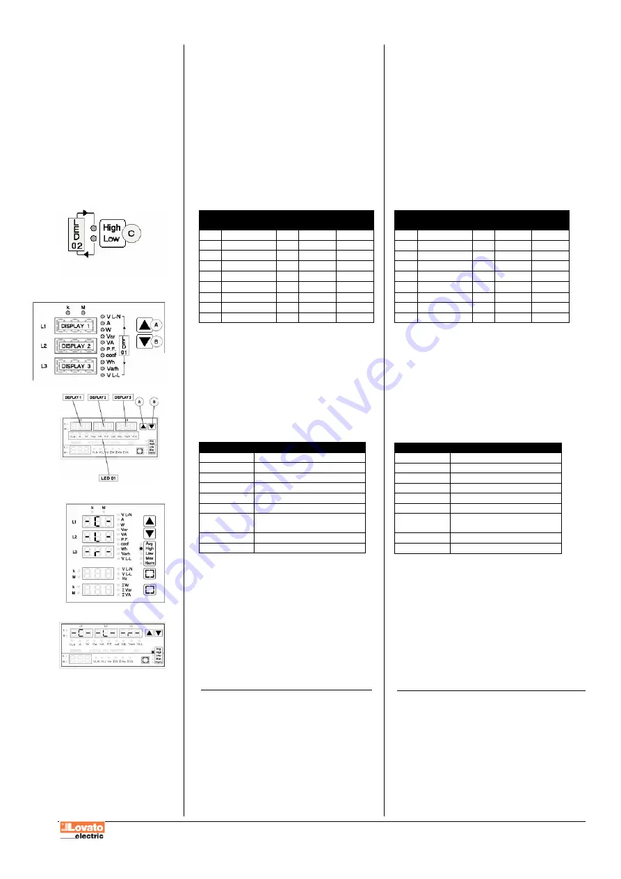
Funkcje przycisków A i B
•
Przyciski A i B służą do wyboru pomiarów
pokazanych w grupie LED01.
•
Pomiary odpowiadające: L1, L2 i L3 pokazane
są na wyświetlaczach 1, 2 i 3.
•
Diody LED
k
i
M
pokazują, że pomiary są wyrażone
w tysiącach lub milionach.
TABELA POMIARÓW GRUPY LED 01:
LED
Funkcja
V L-L
Napięcie międzyfazowe
V L-N
Napięcie fazowe
A
Prąd
W
Moc czynna
var
Moc bierna
VA
Moc pozorna
P.F.
Całkowity współczynnik mocy
(T.P.F)
Wh
Energia czynna pobrana
varh
Energia bierna pobrana
•
W układzie bez przewodu neutralnego, wyświetla
się wewnętrzne napięcie DMK w układzie gwiazdy
•
Całkowity współczynnik mocy jest obliczany
z uwzględnieniem odkształceń harmonicznych prądu
i napięcia
•
Wyświetlacze 1-2-3 w odpowiedniej kolejności,
pokazuje napięcia międzyfazowe L1-L2,L2-L3 i L3-
L1.
•
Wartość pomiaru energii jest wyświetlana
na wszystkich trzech wyświetlaczach począwszy
od góry. Pomiary miernika są wyświetlane z jedną
cyfrą dziesiętną oznaczającą dziesiątą cześć Wh lub
varh
KASOWANIE MIERNIKA Wh
•
Używając przycisków A lub B, należy przejść
na pomiar
Wh
bez zwalniania przycisku, kiedy dany
pomiar jest ustawiony nacisnąć przycisk D
•
Przytrzymując przyciski wciśnięte przez 5 sekund,
kasujemy wartość wybranego parametru.
•
Na wyświetlaczach pokaże się skrót CLr (cleared)
potwierdzający operację kasowania.
With balanced three–phase connection, one CT only must
be connected on phase L1.
Except for voltage values, all the other measures on phase
L2 or L3 are the same as phase L1.
•
With P.04 set at 50 or 60 Hz, viewing is refreshed more
often. See Technical Characteristics.
•
P.05 and P.06 are used to establish which default measure
to view on DISPLAYS 1-2-3-4.
•
P.07 is used to fix the reset time of the configuration made
with P.05 and P.06.
•
P.11 is used to set the integration time for the peak or
thermal current calculation.
•
P.41 to P.45 set the serial communication. Refer to the
separate Addendum manual.
P.05
Measure
P.06
DMK
measure
1 V L-L
1 V L-L
2 V L-N
2 V L-N
3 A
3
Hz
4 W
4
W
5 var
5
var
6 VA
6
VA
7 P.F.
8 Wh
9 varh
MEASURE VIEWING
A and B key functions
•
A and B keys are used to select the measure indicated by
LED 01 group.
•
The measures related with phases L1, L2 and L3 are
respectively shown on DISPLAYS 1, 2 and 3.
•
k
and
M
LEDs at the top respectively indicate that
measures are expressed in thousands or millions.
LED 01 GROUP MEASURE TABLE:
LED
FUNCTION
V L-L
Line voltage
V L-N
Phase voltage
A
Current
W
Active power
var
Reactive power
VA
Apparent power
P.F.
Total Power Factor
(T.P.F)
Wh
Imported active energy
varh
Imported reactive energy
•
Without neutral connection , the internal DMK star voltage
is shown.
•
Total power factor is calculated taking into consideration
the voltage and current harmonic distortion.
•
DISPLAYS 1-2-3 respectively view L1-L2, L2- L3 and
L3-L1 line voltages.
•
The value of the energy meters is displayed on all three
displays starting from the top towards the bottom. The
meter measures are displayed with one decimal signifying
hundreds for Wh or varh.
Wh METER CLEARING
•
Using key A or B move to the
Wh
measure without
releasing the key once the required measure has been
reached.
•
Keeping it pressed for 5 consecutive seconds, the value of
the chosen measure is cleared.
•
The wording CLr (cleared) is shown on the display to
confirm it has taken place.


