INTRODUCTION
Translation of the original instructions
9
Electrical technical data table
MODEL
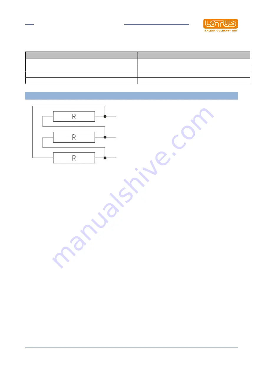
WIRING DIAGRAMS
F10D-64ETX
C
F18D-64ETX
F2/10D-66ETX
C + C
F2/8D-64ETX
PREDISPOSITION 440V~3
Страница 1: ...g instructions ELECTRIC FRYERS FOR PROFESSIONAL USE F10D 64ETX F2 10D 66ETX F18D 64ETX F2 8D 64ETX Model LIBR ISTR FDX POT Code 563022401 Review 1 Edition date 22 04 2020 Language English LOTUS S p A...
Страница 2: ...ctrical and electronic equipment 11 2 3 Technical data table 11 3 INSTALLATION 12 3 1 Delivery checks 12 3 2 Removing the packaging 12 3 3 Mechanical installation 12 3 4 Electrical gas connections 12...
Страница 3: ...INTRODUCTION Translation of the original instructions 3 1 INTRODUCTION 1 1 Installation drawing FIG 1 F10D 64ET F2 10D 66ET...
Страница 4: ...INTRODUCTION Translation of the original instructions 4 MODEL A B C F10D 64ETX 400mm 200mm 87 5mm F2 10D 66ETX 600mm 150mm 37 5mm B Electrical connection...
Страница 5: ...INTRODUCTION Translation of the original instructions 5 FIG 2 F18D 64ET B Electrical connection...
Страница 6: ...INTRODUCTION Translation of the original instructions 6 FIG 3 F2 8D 64ET B Electrical connection...
Страница 7: ...ol knob to zero but the system remains operational until the problem that caused the intervention is resolved Contacts 80 and 81 are provided to enable the fryer to be controlled from a remote locatio...
Страница 8: ...tions 8 WIRING DIAGRAM C 1 Cicada 2 Switch 3 Microswitch 4 Power supply terminal board 5 Heating element 6 Resistance voltage drop 7 White indicator light 8 Red indicator light 9 Green indicator light...
Страница 9: ...INTRODUCTION Translation of the original instructions 9 Electrical technical data table MODEL WIRING DIAGRAMS F10D 64ETX C F18D 64ETX C F2 10D 66ETX C C F2 8D 64ETX C C PREDISPOSITION 440V 3...
Страница 10: ...electrical safety of this equipment is only ensured when it is correctly connected to an effective ground earth system as required by current electrical safety standards The manufacturer cannot be he...
Страница 11: ...nt and human health may be due to the misuse of the same equipment or parts of it The symbol next to the rating plate indicates the obligation of separate collection The penalties provided for in the...
Страница 12: ...nding the heat emitted by this appliance Connect the water supply if necessary Caution Do not install the appliance near equipment machines used in cold processes If the appliance has to be installed...
Страница 13: ...in our production range A minimum distance of 10 cm between appliances must be respected to prevent contact with any walls made of flammable material furthermore appropriate measures should also be a...
Страница 14: ...cross section for the power of the appliance see technical data table EQUIPOTENTIAL The appliance must be connected to an equipotential system The connecting screw is located on the rear of the appli...
Страница 15: ...leaning or maintenance operation Fill the tank with oil up to the lower reference mark 4 2 Turning the appliance on off Turn on the switch located upstream of the appliance Turn the knob from 0 to the...
Страница 16: ...ass has melted 4 4 Emptying the tank The user is required to have a suitable recipient for emptying the oil This recipient must be made of heat resistant material and must ensure that during the empty...
Страница 17: ...e and its safety systems Warning For maintenance replacement of components order and use only original spare parts Replacing parts must exclusively be performed by authorised and or qualified personne...
Страница 18: ...g the heating element Unscrew the two 8 mm screws that fasten the bracket to the heating element and pull out the bracket until it can be removed At this point the heating element can be removed from...
Страница 19: ...are available commercially but a diluted solution of acetic acid can also be used To clean STAINLESS STEEL appliances it is advisable to use detergents specifically formulated for this material For m...