www.lorexcctv.com
SG21CD7444UQ-A80
Page 1
Version 1.01
STEP 1
SETTING UP YOUR MONITOR FIRST
Package Contents
3
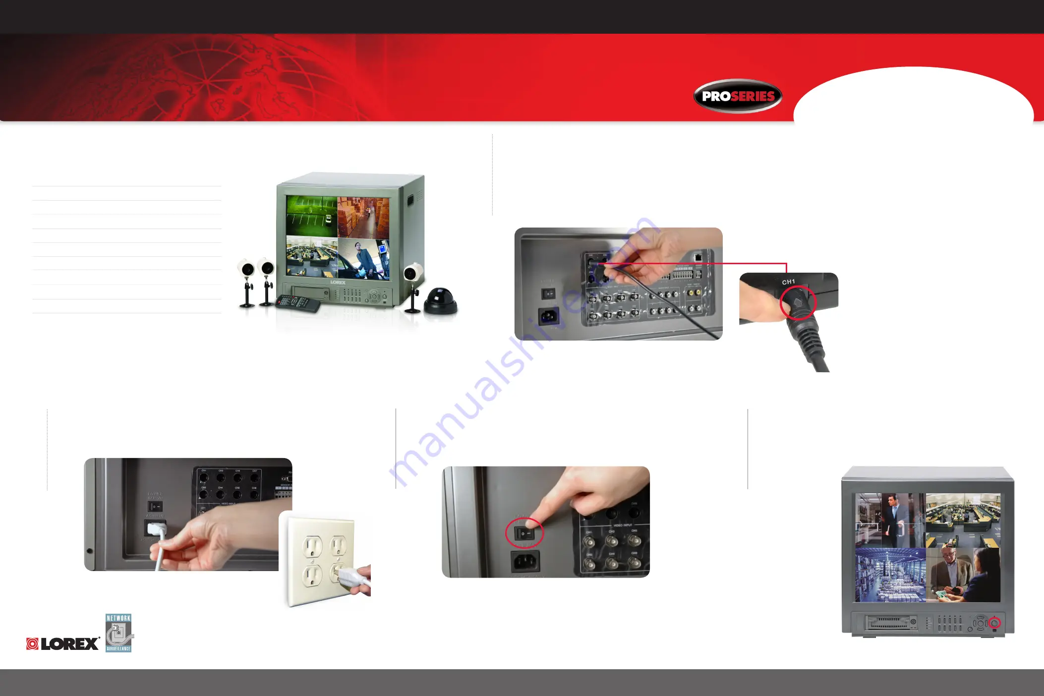
Turn the Master power switch located at
the back of the monitor ‘ON’.
4
Press the Power button. Wait for the
monitor to check internal settings.
The four camera images will now
appear.
For detailed
monitor setup
information,
please refer
to your
system
owners
manual.
Information in this document is subject to change without notice. As our products are subject to continuous improvement, Lorex Technology and our subsidiaries reserve the right to modify product design, specifications and prices, without notice and without incurring any obligation. E&OE © 2006 LOREX. All rights reserved.
NOT INCLUDED: BROADBAND ROUTER, COMPUTER & ETHERNET NETWORK CABLE
BACK OF THE MONITOR
FRONT OF THE MONITOR
1 - 21” Colour Monitor with Built-in Digital Video Recorder
1 - 80 GB Hard Disk Drive (installed inside hard drive bay)
3 - Colour Cameras
1 - Colour Dome Camera
3 - Camera stands
4 - 56 ft Extension Cables for camera
1 - USB cable
1 - Power Cord
1 - mCAM Security Monitoring Software CD
1 - Owners Manual
1 - Quick Set-up Guide
10:00
STEP 1 SHOULD TAKE
APPROXIMATELY 5 - 10
MINUTES TO COMPLETE
1
Connect cameras to the monitor
BACK OF THE MONITOR
4 Color cameras are included with the Observation System. These cameras have
a single cable, and receive power directly from the Observation System.
1. Connect the female end of the supplied 57’ extension’ cable to the camera
2. Connect the male end of the supplied 57’ extension cable to an open DIN
channel on the back of the Observation System. Continue connecting
additional DIN cameras.
NOTE: The arrow mark on top of the 6 PIN camera
cable(s) should face UP while inserting the 6 PIN
camera cable(s) to the Monitor’s 6 PIN connector(s).
2
Connect one end of the power adapter (standard
power cable) to the monitor, the other end to an
electrical outlet.
BACK OF THE MONITOR


