background image

51

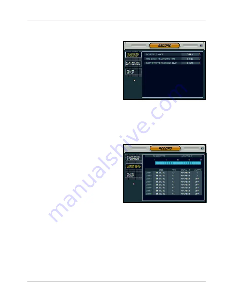
Recording Menu Controls

Recording Operations

• 

SCHEDULE MODE

- Sets the Scheduled 

Recording Mode to Daily or Weekly.

• 

PRE EVENT RECORDING 

- When an 

alarm is detected, the Pre Alarm will 
begin recording before the Alarm was 
detected (retrieved from video cache). 
The Pre Alarm Recording Time can be 
set to between 1~5 seconds. 

• 

POST EVENT RECORDING

 - When an 

alarm is detected, the Post Alarm will 
remain recording for the specified time. 
The Post Alarm Recording Time can be 
set to between 5~180 seconds. 

Continuous / Motion Setup

• 

PARAMETER MODE 

- Contains the 

general recording parameters for each 
camera

• 

SCHEDULE MODE

 - Contains the 

schedule recording settings for each 
camera.

NOTE: Audio Recording ONLY works on 
Channels 1~4 on the 4 CH Model, and 
Channels 1~2 on the 8/16 CH Models.

Содержание L500 Series

Страница 1: ...Copyright 2007 LOREX Technology Inc www lorexcctv com Series Includes L504 4CH L508 8CH L516 16CH DIGITAL VIDEO SURVEILLANCE RECORDER Instruction Manual English Version 4 0 SERIES L500 Series ...

Страница 2: ...RE CAUTION TO PREVENT ELECTRIC SHOCK MATCH WIDE BLADE OF PLUG TO WIDE SLOT FULLY INSERT Thank you for purchasing this Digital Video Surveillance Recorder Lorex is committed to providing our customers with a high quality reliable security product The L500 Series combines advanced performance with easy operation and great economy to offer a whole new class of digital video recorders to high end resi...

Страница 3: ... cord and if its appearance indicates damage or deteriorated insulation have it replaced by your service technician 7 Power Cord Protection Power supply cords should be routed so that they are not likely to be walked on or pinched by items placed upon or against them paying particular attention to cords at plugs convenience receptacles and the point where they exit from the video product 8 Ventila...

Страница 4: ...r can prevent fire electric shock or other hazards 16 Safety Check Upon completion of any service or repairs to this video product ask the service technician to perform safety checks recommended by the manufacturer to determine that the video product is in safe operating condition 17 Wall or Ceiling Mounting Any cameras provided with this system should be mounted to a wall or ceiling only as instr...

Страница 5: ...cted z Consult the dealer or an experienced radio or television technician for assistance Lorex TECHNOLOGY INC http www lorexcctv com NOTE This equipment has been certified and found to comply with the limits regulated by FCC EMC and LVD Therefore it is designated to provide reasonable protection against interference and will not cause interference with other appliance usage However it is imperati...

Страница 6: ...ideo channels in another location Independent Channel Control Customize the recording parameters to the surveillance application for each camera on the DVR For Example z Cam 1 is pointing at a Cash Register The DVR allows you to set the parameters for real time recording at high resolution so all data is captured in Real Time z Cam 2 is recording the Front Door The DVR allows you to set the parame...

Страница 7: ...25 Menu Navigation Controls Tips 27 System Setup Controls 28 Display Menu 29 OSD Onscreen Display 29 MONITOR 8 16 CH ONLY 30 SEQUENCE 8 16 CH ONLY 31 SEQUENCE SETUP MODE 32 SPOT OUT 8 16 CH ONLY 33 Camera Menu 34 CAMERA TITLE 34 COLOR SETUP 35 PTZ SETUP 35 PTZ PROPERTIES 36 MOTION SENSOR 36 Sound Menu 37 SOUND 37 BUZZER 37 System Menu 38 DATE TIME 38 NETWORK 39 NETWORK 40 MAIL SETUP 40 USER MANAGE...

Страница 8: ... IP Address 59 Setting Up Your DDNS Account 60 Router Port Forwarding 62 DDNS SETUP 63 Troubleshooting 64 DVR Specifications Appendix 1 65 67 Lorex Client Software Requirements Appendix 2 68 Connecting a Slave Spot Out Monitor Appendix 3 69 Connecting Motion Alarm Device Appendix 4 70 Connecting PTZ Cameras Appendix 5 71 Full Connectivity Diagram Appendix 6 72 Hard Drive Replacement Addition Appen...

Страница 9: ... the following components CHECK YOUR PACKAGE TO CONFIRM THAT YOU HAVE RECEIVED THE COMPLETE SYSTEM INCLUDING ALL COMPONENTS SHOWN ABOVE REMOTE CONTROL POWER ADAPTOR DIGITAL VIDEO SURVEILLANCE RECORDER HARDWARE SOFTWARE MANUALS QUICK START GUIDE SOFTWARE CD ...

Страница 10: ...ED is ON ALM Indicates that the unit has an active ALARM 4 PLAYBACK NAVIGATION CONTROLS Controls the playback of video and navigates in the main screen in Menu and Search Modes Playback Controls REVERSE SPEED BUTTON Reverses the playback of the currently displayed Video press to change the reverse playback speed 2x 4x 8x 16x 32x 64x INCREASE SPEED BUTTON Increases the playback speed in both Forwar...

Страница 11: ...layback menu PLAY BUTTON Starts the playback of the currently displayed Video ESCAPE BUTTON Exits the onscreen playback exits the playback menu DECREASE SPEED BUTTON Decreases the playback speed in both Forward and Reverse play 2x 4x 8x 16x 32x 64x PAUSE BUTTOn Pauses the video playback Navigation Controls NAVIGATION CONTROLS Move Up Down Left and Right in all menus ENTER BUTTON Select an option i...

Страница 12: ...ickly forward the playback 7 CONTROL BUTTONS SCR MODE Press to display a Single Channel or 4 8 or 16 channel views SEARCH BUTTON Opens the Search Menu to view previously recorded data Refer to the Search Section of this manual for detailed search options MENU BUTTON Opens the Main Menu to configure the DVR Displays the DVR Information when in Channel View PTZ BUTTON Accesses the PTZ Pan Tilt Zoom ...

Страница 13: ...or 16 Channels The numbers are also used to enter the Password when logging into the DVR 9 POWER SWITCH Press to turn the DVR display ON OFF Press and Hold the button for 6 seconds to turn the DVR ON OFF the default password is 1234 10 USB PORTS Provides connection ports for USB Flash Drives thumbsticks USB Hard Drives and Optional Mouse not included 1 2 3 4 5 6 8 9 10 7 ...

Страница 14: ...of the buttons is slightly different Refer to the descriptions in the Front Panel 4 Channel section for details on functions 1 DVD RW DRIVE 2 IR LED FOR REMOTE CONTROL 3 CONTROL BUTTONS SCR MODE SEARCH MENU AND PTZ 4 PLAYBACK NAVIGATION CONTROLS 5 HOLD BUTTON 6 SPEED CONTROL DIAL 7 CHANNEL SELECT BUTTONS 8 or 16 8 INDICATOR LEDs 9 POWER BUTTON 10 USB PORTS 1 2 3 4 5 6 8 9 10 7 ...

Страница 15: ...ectly reflects the current onscreen images 4 RCA AUDIO INPUTS Channel 1 4 Audio inputs for BNC type cameras with standard RCA Audio output 5 ALARM BLOCK INPUT OUTPUT RS 485 PTZ TERMINALS These terminals are used to connect External alarm devices such as a motion sensor door alarm sensor or time lapse VCR for Alarm Recording The block is also used to connect Relay and RS 485 Connection types These ...

Страница 16: ...lects the current onscreen images 10 AUDIO OUT Audio Output port to connect the unit to a secondary DVR or TV 11 ETHERNET PORT Located on the back of the unit above the Alarm Block terminals Connects the monitor to a router for connection to the internet Refer to the appendices for Remote Connection setup 12 RS 232C PORT These terminals are used to connect Relay and RS 232C Connection types 13 DC ...

Страница 17: ... PAL Switch unit automatically switches between NTSC and PAL No SVHS Port No RS 232C Port The placement of the ports is slightly different Refer to the descriptions in the Back Panel 4 Channel section for details on functions 1 BNC VIDEO INPUTS 8 OR 16 BASED ON MODEL 2 MONITOR OUT 3 AUDIO IN 2 CHANNEL MENU CONFIGURABLE 4 ALARM BLOCK INPUT OUTPUT RS 485 PTZ TERMINALS 5 SPOT OUT 6 AUDIO OUT 7 ETHERN...

Страница 18: ...n the current image NAVIGATION AND PLAYBACK Controls the playback of video Navigates in MENU and SEARCH mode Adjusts the zoomed area in ZOOM mode NOTE All Buttons described above function the same as the Front Panel buttons see the 4 Channel Front Panel section for detailed information Buttons without descriptions do not pro vide functionality to this unit REMOTE ID Configure when using multiple s...

Страница 19: ...nd Right Buttons to open menus and change options LEFT BUTTON Double click on a Channel in QUAD or other views to view the single camera in full screen Click to use the Controls in PTZ Mode Click to select options in Menu Recording and Search Mode Use the left button to change settings select dates and perform other options RIGHT BUTTON Opens a submenu to access a list of options ...

Страница 20: ...dual Camera Display Each channel displays the Camera Name and Recording Status Record Pre Record C Continuous M Motion A Alarm NOTE If a new HARD DRIVE is detected the system will prompt you to FORMAT the drive If you do not choose to format the HARD DRIVE the drive will not be detected by the system If you choose to FORMAT a drive in this way the drive will no longer be readable by a regular PC w...

Страница 21: ...at the network connection is stable Blue Indicates that the network connection is experiencing difficulties Red Indicates that the network is unstable Display Modes Cameras can be displayed in several different modes by pressing the Display Button on the front panel of the system or by pressing the SCR Button on the Remote Control Network Indicators Single Channel Quad 4 Channel 6 Channel 8 Channe...

Страница 22: ...ra is not displayed an empty blue screen is displayed instead of the Video Covert cameras are configured from the Menu Camera Volume Display Mode Displays the Camera currently sending Audio The number of available audio channels varies by model 4 Audio on 4 CH Model 2 Configurable Audio on the 8 and 16 CH Models The Camera Volume can be controlled using the up and down arrows Camera with Audio Vol...

Страница 23: ...to access the PTZ Control Screen The onscreen icons represent buttons on the front panel and remote control up down left right The Camera can be adjusted using these buttons Press the Return Button to exit PTZ Mode Press the PTZ Button a second time to access the Focus Control Screen The onscreen icons represent buttons on the front panel and remote control up down left right TheCameracanbe adjust...

Страница 24: ...f the System Only the ADMIN can turn the unit ON OFF The System will NOT continue to record while the unit is off The LED indicators on the front of the System will be OFF NOTE There are 3 available system permission levels Admin Configured into the System by default Manager Permission level when adding a new user to the System provides Access to Search and view live video remote User Permission l...

Страница 25: ... the Arrow Keys on the front panel or remote control Once the date has been located press the Enter button to accept the date and to access the Time Search on the right side of the screen Press and Hold the arrow keys to select the Time increments of 1 minute Pressing the button without holding will increment 15 minutes Press the Enter button to start the playback Press the Return button to stop p...

Страница 26: ...nts will be displayed Navigate to an event and press the Enter button to start the playback Press the Return button to stop the playback and return to the Event Search screen Playback and Navigation Controls Play Button Normal Speed Playback Reverse Playback Button Normal Speed Reverse Playback Pause Button Pause the onscreen Playback The Fast Forward and Reverse playback buttons can be used while...

Страница 27: ... the Front Panel or Remote Control Use the ENTER key to choose the letters numbers and symbols Select the APPLY button once the setup is completed Active Option Indicator NOTE Once changes have been made select the APPLY button at the bottom of the screen and press the ENTER button on the front panel or remote control Changes will be saved at this time exiting the menu without applying the changes...

Страница 28: ...s the RETURN button NOTE Options may differ between the 4 Channel and the 8 16 Channel Models Carefully review the following menu options for details KLIJ ENTER RETURN Scroll UP DOWN LEFT RIGHT within a menu option Press this button to select and change the values in a menu option Complete modifications of a menu option exit a menu DISPLAY Setup of display options CAMERA Setup for individual Camer...

Страница 29: ...rough the SPOT OUT Port OSD Onscreen Display Status Bar Turns the status bar ON OFF The status bar displays z Recording State Recording Red Pre recording Green z Network Indicators z Time and Date z HDD Free z Refer to Recording Settings Camera Title Turns the display of the Camera Titles ON OFF Event Icon Turns the Event Icon display ON OFF Border Turns the separation border ON OFF when the displ...

Страница 30: ...tion Sensor blocks from 0 5 MONITOR 8 16 CH ONLY Sequence Dwell Sets the cycle time when the system is in Sequence Mode between 1 60 seconds Spot Out Dwell The length of time to display a camera in Spot out mode De Interlace Mode Removes the screen spread when set to ON Alarm Pop Up Mode Set to ON OFF Switches the screen display to any channel when an Alarm is detected Alarm Pop Up Dwell Determine...

Страница 31: ...e z Sequence Title Enter a title for the New Sequence z Activation Turn the Sequence ON OFF only one sequence can be active at a time z CANCEL Button Cancels the addition of the New Sequence z SAVE Button Saves the New Sequence and moves to the New Sequence Configuration screen Once the New Sequence has been created the Sequence Setup Mode screens appear These screens will set the sequence pattern...

Страница 32: ...e 3 Press the Number Keys to Select channels to be displayed in Sequence all squares must have an assigned number Right click to choose CH 6 Press the SEQ button on the Front Panel to switch to Sequence display 5 Press the RETURN button when complete Select SAVE EXIT Right Click to Exit 4 Choose the next Display Mode up to 16 additions SEQUENCE SETUP MODE ...

Страница 33: ...d camera video to a secondary Monitor via the Spot Out Port on the back of the unit Check or Uncheck the selected Cameras to have the video sent to a Secondary Monitor in Sequence NOTE Any cameras NOT checked will not be sent as video to the Spot Out Monitor ...

Страница 34: ... the onscreen display of the Camera ON OFF Covert Cameras continue to record however the camera is not displayed onscreen This feature is commonly used in situations where the Monitor is located in a public area and a camera should not be displayed i e Located in a Cash Count room or directed at a Cash Register Title Sets the name for the individual camera 0 9 A Z up to characters by using the Vir...

Страница 35: ...m Address Select the physical address location of the PTZ Camera as connected to the rear PTZ Control Block Refer to the appendices for details PTZ Protocol Select the Protocol for the PTZ Camera See the list of compatible protocols below Consultthe Owners Manual of the PTZ Camera for further details Baud Rate Setup for the PTZ Communication Speed 2400 4800 9600 19200 38400 BPS Compatible PTZ Prot...

Страница 36: ... Motion Sensitivity for the individual camera between 1 low 10 high Area Setup Opens the Area Setup for the camera CONFIRMATION SCREEN Select All Selects all areas Deselect All Clears all areas Cancel Cancels Area Setup Save Exit Saves the settings AREA SETUP Move the Cursor by using the directional arrows located on the Front Panel or Remote Control Press Enter to select or deselect a Region Pres...

Страница 37: ...Audio Monitoring Channel Select the channel for Listen in Audio Channels 1 4 on 4CH 1 2 on 8 16CH NOTE Listen In Audio only works with Channels 1 4 4CH or 1 2 8 16CH Network AudioTX Sets Network Audio Transmission to ON OFF Network Audio RX Sets Network Audio Receive to ON OFF Please refer to the Recording Settings when specifying an Audio Channel on the 8 16 CH models BUZZER Keypad Turns the Keyp...

Страница 38: ... format MM DD YYYY YYYY MM DD etc Time Format Sets the Time Display format to either 12 or 24 hour display Network Time Server Setup Synchronizes the system to the specified remote time server Select the SYNC button to connect to the remote server and synchronize the time Timezone Setup Selections for the local Time Zone i e EST CST PST The DST Daylight Savings Time can be set to ON OFF NOTE If th...

Страница 39: ...ering the IP address Lorex offers a free DDNS Service at http ddns strategicvista net z If you use the DDNS there is no need to enter the IP Address with every connection z Navigate to the DDNS website to configure the free account Enter your specific information as provided at the DDNS Site z Refer to the Network Setup instructions in the appendices for information on using the Free DDNS Service ...

Страница 40: ...ximum Data Transfer speed for the remote connection default of 8192 KB sec MAIL SETUP The Mail Setup uses your existing Email settings to send notifications and alerts Default Server Click to use the system default Server Enter the Email server information for your IP Port Default port of 25 Security Sets the Mail Security ON OFF based on the requirements of the mail provider User Enter the User N...

Страница 41: ...n ID Name for the new user Password Enter a password for the New User Group Enter the permissions level z Admin Highest Level Access The Admin has full system access z Manager Mid Level Access The Manager can use the Search Functions and view live video z User Low Level Access The User Can view cameras without changing settings Email Enter the Email address for the New User Email Notification Turn...

Страница 42: ...p and Search Menus System Information Screen Displays the System Information The IP address and MAC address are necessary for setting up the DDNS Server IP Address Displays the IP address assigned to the System MAC Address Displays the unique MAC address assigned to the unit This address is hard coded to the unit and cannot be changed Disk Capacity Displays the Total Hard Drive space and the amoun...

Страница 43: ...on by selecting the PRESS button The USB device will be recognized by the system Press the START button to display the available firmware Select the Firmware and press ENTER A prompt will appear confirming the Update Press OK to begin the update process The System must be restarted for the Changes to Take effect Press OK and exit the Menu The System will automatically Reboot NOTE The System will n...

Страница 44: ...sert the Memory stick into the System and select the Save option to save settings z A Success message indicates that the backup was completed z If the device is not detected a message will indicate that No storage device was found Insert the Memory stick into the System and select the Load option to restore settings This is recommended after initial setup and installation is complete CONTROL DEVIC...

Страница 45: ...ted BUZZER OUT Turns the audible Buzzer ON OFF for selected event types E MAIL NOTIFICATION Sends and E Mail notification when a selected event occurs based on User Configuration settings HDD EVENT Smart Alarm Sets the Smart Alarm ON OFF An alarm occurs when errors are detected with the drive Check Interval Sets the Hard Drive check interval 1 24 hrs This setting allows the System to self check th...

Страница 46: ...Closed status z N C Normally Closed Select for an Alarm that has a Normally Closed circuit such as a Window Sensor An Alarm will occur when this is changed to a Opened status ALARM OUT Sends an Alarm Out signal to a device such as a Manual Door or independent Light Buzzer Alarm when an Alarm In event is detected Channel Select a Channel to configure Mode Setup Reacted Relay as either Latched or Tr...

Страница 47: ... OFF BUZZER OUT Generates a Buzzer when an alarm is detected Operation Enables Disables the buzzer for selected Event Alarm types Mode Set the Reacted Relay to either Latched or Transparent Mode HDD Event Generates a Buzzer alert when a Hard Drive event occurs set to ON OFF Duration Sets the Buzzer time 5sec 5minoruntilauserlogsintothesystem Alarm Generates a Buzzer Alarm when an Alarm Event is de...

Страница 48: ...cation ON OFF HDD Event A notification is sent if a Hard Drive event is detected set to ON OFF Notifications can be enabled for each channel for z Alarm z Video Loss z Motion can be selected NOTE Emails will be sent at 15 minute intervals for the duration of the Event ...

Страница 49: ...erwrite Determines how data is maintained when the Hard Drive is full z ON When Overwrite is set to ON data will be overwritten when the Hard Drive is full starting with the Oldest recording z OFF When Overwrite is set to OFF the data will not be overwritten when the Hard Disk is Full Recording will Stop and the Buzzer will be Activated Format Erases all Hard Drive data z Press start button A warn...

Страница 50: ...e option and press the ENTER button To exit a SUBMENU press the RETURN button To exit the MAIN MENU press the RETURN button Recording Menu Options KLIJ OK MENU Scroll UP DOWN LEFT RIGHT within a menu option Press this button to select and change the values in a menu option Complete modifications of a menu option exit a menu RECORDING OPERATIONS General setup of Recording Features CONTINUOUS MOTION...

Страница 51: ... can be set to between 1 5 seconds POST EVENT RECORDING When an alarm is detected the Post Alarm will remain recording for the specified time The Post Alarm Recording Time can be set to between 5 180 seconds Continuous Motion Setup PARAMETER MODE Contains the general recording parameters for each camera SCHEDULE MODE Contains the schedule recording settings for each camera NOTE Audio Recording ONL...

Страница 52: ...nnel can be set to 1 2 3 7 15 or 30 Frames per second real time video capture from a shared pool of 120 FPS Quality Sets the video recording quality to Low Standard High or Highest Audio The Audio Recording Settings work differently on the 4 CH and 8 16 CH Models z 4CH Model Turn the Audio recording ON OFF for each channel z 8 16 CH Models The systems share 2 audio ports Set the audio port to 1 or...

Страница 53: ...ighlighted in Green and press ENTER again to open the settings window None No recording schedule is set Continuous The system constantly records the camera based on the hourly setting Motion Only starts the recording if motion is detected in the selected time interval Select the RETURN button to apply the changes Once settings have been adjusted for the hour the changed time block will be displaye...

Страница 54: ... for each camera to 352x240 704x240 or 704x480 FPS Sets the Frames Per Second for recording for each channel Each channel can be set to 1 2 3 7 15 or 30 Frames per second real time video capture from a shared pool of 120 FPS Quality Sets the video recording quality to Low Standard High or Highest Audio The Audio Recording Settings work differently on the 4 CH and 8 16 CH Models z 4CH Model Turn th...

Страница 55: ...to enter the Camera Selection window and navigate using the arrow keys Select an Hour highlighted in Green and press ENTER to set to Alarm highlighted or None no highlight Select the RETURN button to apply the changes Once settings have been adjusted for the hour the changed time block will be displayed as NONE ALARM ...

Страница 56: ... To exit the MAIN MENU press the RETURN button Archiving Options Select Device Displays all detected backup media devices USB Flash Memory Stick or USB Hard Drive From Select the Start Time and Date for Backup To Select the End Time and Date for Backup Mode Select the Backup Mode z Burning Copies the data to the backup device z Burning Erasing Copies the data to the backup device then deletes the ...

Страница 57: ... Size of the Log File Select OK to begin the backup The Writing status window displays the completion state of the Backup in The Extracting status window displays the completion state of the Extraction of previously archived data in The Erasing status window displays the completion state of the Erasing of previously archived data in Error Messages Error dialogue when the archive process fails Erro...

Страница 58: ... the router prior to powering on the system This allows the system to communicate on your network 2 Find the IP address of your DVR through the Menu System on the unit 3 Set up a web account at http DDNS strategicvista net 4 Enable PORT FORWARDING on your Router 5 Install the Software onyour PC See the Software Installation Guide provided with this System for installation requirements and details ...

Страница 59: ...ton 2 Navigate to the System Menu option Press the Enter button to access the System Menu 3 Navigate to the System Management menu and press the Enter Button to access the settings 4 Select the System Information option and press the Enter Button to display the System Settings Finding Your External IP Address You will need to have your External IP address to set up your DDNS account One of the fas...

Страница 60: ...ategicvista net 2 Select the Create Account option from the list on the left side of the screen 3 Complete the Account Information fields with your personal information 4 Complete the System Information fields Product License Select your product model from the Product License drop down menu Product Code MAC Address Locate the MAC address of your recorded while loading the System URL Request Choose...

Страница 61: ...rvice provider User Name Domain Name Password dns1 strategicvista net tomsmith1 tomsmith your password User Name ________________________________________________________ Domain Name __________________________________________________________ Password __________________________________________________________ Only the first part of the Domain Name is required for setup on the SG19LD804 161 System If...

Страница 62: ...nd data to your internal network it sends this data to the external IP address of the Router The Router then needs to decide where this data is to be sent to This is where setting up Port Forwarding becomes important Port Forwarding tells the router which device on the internal network to send the data to When you set up port forwarding on your Router it takes the data from the external IP address...

Страница 63: ...through Internet Explorer 1 Access the Main Menu Setup screens and navigate to the SYSTEM option Press the ENTER button to access the setup 2 Navigate to the NETWORK option Press the Enter button to access the Network settings Select the DDNS Server option and press the ENTER button to enter the DDNS SETUP 3 Enter the information received in email including the password Select OK to save the setti...

Страница 64: ...est the outlet with another plugged device such as an electric calculator or phone charger If the unit is connected through a power bar or surge protector try bypassing the bar and connecting the power directly to the wall outlet Confirm that the unit is powered on LED indicators on the front should be ON Problem The image on the DVR appears but does not have sound Check Check the VOLUME Check the...

Страница 65: ...NTSC 704x576 PAL Audio Inputs 4 x Line In RCA Sockets 4 CH 2 x Line In RCA Sockets 8 16 CH Audio Outputs 1 x Line Out RCA Socket Audio 2 Way Audio Conference via network Compression Standard MPEG4 Image Size 3 5 KB 352x240 NTSC 352x288 PAL 5 10 KB 704x240 NTSC 704x288 PAL 6 16 KB 704x480 NTSC 704x576 PAL Video Inputs 8 x 1Vp p CBVS 75ohms BNC Looping Inputs Hard Disk Capacity 2 x 500GB HDD up to 1...

Страница 66: ...ideo simultaneously Local Remote Recording Speed 352x240 120 100 NTSC PAL 704x240 60 50 NTSC PAL 704x480 30 25 NTSC PAL Record Scheduling Daily Weekly and Hour Specific Pre Post Alarm Pre Alarm 5 Seconds Post Alarm 3 Minutes programmable per camera Event Log Search Up to 100 000 for user login logout configuration changes remote access and connects disconnects Playback Single Quad or 8CH Simultane...

Страница 67: ...ture Rating 23 F 122 F 5 C 50 C Housing Steel Metal Color Silver Dimensions WxDxH 14 2 x 15 3 x 2 6 360 mm x 389mm x 66 mm Weight 8 6 lbs 3 9 kg As our products are subject to continuous improvement Lorex Technology Inc and its subsidiaries reserve the right to modify product design specifications and prices without notice and without incurring any obligation E OE ...

Страница 68: ...lity Operating System Windows 2000 Windows XP Home Edition Windows XP Professional Windows Vista Processor Pentium 4 1 5 GHz Processor or equivalent Memory 256 MB RAM Hard Drive 50 MB Installation space required Additional Hard Drive space required for recording Recorded file size will vary depending on recording quality settings Operating System Windows XP Home Edition Windows XP Professional Win...

Страница 69: ...tor can only display data as it is sent from the DVR based on settings in the Spot Out Menu options MONITOR OUT Displays exactly what is shown from the DVR Camera View Menus etc to a TV or VCR SPOT OUT Displays Cameras in Sequence mode regardless of the display on the DVR i e Camera Views Menus Playback etc to a TV or VCR LOOP OUT 4 CH ONLY Displays the video output from a single Camera to a TV or...

Страница 70: ... A Window sensor unit has been installed on Alarm Block port 4 When this sensor is activated the camera on DIN or BNC VIDEO port 4 will become active if enabled in the MENU on the DVR Installing a Sensor 1 Connect the GROUND Cable to the GND port on the Alarm Block on the DVR 2 Connect the SIGNAL Cable to a numbered port 1 8 To start ALARM RECORDING on the System refer to the Menu Configuration se...

Страница 71: ...meras are available at http www lorexcctv com Installing a PTZ RS 445 Type PTZ Camera 1 Connect the Transmit Cable to the D port on the PTZ Control Block on the DVR 2 Connect the Receive Cable to the D port on the PTZ Control Block on the DVR 3 Connect the Camera to BNC Channel 1 4 Configure PTZ Menu options The PTZ Camera Settings will depend on the Type of Camera refer to the specific Camera Man...

Страница 72: ...ndix 6 Full Connectivity Diagram Appendix 6 The following diagram outlines a general set of connections available with the DVR DVR SENSOR Not Included PC Not Included ROUTER Not Included SLAVE SPOT OUT MONITOR Not Included BNC CAMERAS ...

Страница 73: ...ase Replacing the Hard Drive Remove the Drive Bracket from the DVR by removing the 4 screws Remove the screws holding the Hard Drive into the Drive Bracket Remove the drive cables and drive from the Bracket Set the Jumpers on the Hard Drive to MASTER Refer to the General Jumper Pin Setting on HDD Surface generally located on a sticker on the top of the drive NOTE Use a Hard Drive Model with a powe...

Страница 74: ... DRIVE VIEWER software included on the CD provided with this unit NOTE Do NOT turn off the System while the drive is formatting This can cause problems with the Hard Drive Adding a Second Hard Drive Remove the Drive Bracket from the DVR by removing the 4 screws Set the Jumpers on the secondary Hard Drive to SLAVE Refer to the General Jumper Pin Setting on HDD Surface generally located on a sticker...

Страница 75: ...cording Calculation Resolution Set the recording Resolution to CIF 352x240 2CIF 704x240 or D1 704x480 Quality Set the recording Quality to Low Standard High or Highest FPS Set the Frames Per Second for the recording to 1 2 4 8 15 or 30 FPS HDD Size Select the size of the System Hard Drive 160 GB installed HDD is included with this System 2 Press the CALCULATE button The Software will use all confi...

Страница 76: ... the Front Panel or Remote Control To enter a sub menu navigate to the option and press the ENTER button To exit a SUBMENU press the RETURN button To exit the MAIN MENU press the RETURN button Changing the Date and Time Setting the correct date and time for your system is important Once the date and time have been set correctly it is highly recommended that you format your Hard Drive 1 Enter MENU ...

Страница 77: ...D etc Time Format Sets the Time Display format to either 12 or 24 hour display Network Time Server Setup Synchronizes the system to the specified remote time server Select the SYNC button to connect to the remote server and synchronize the time may also use a time server of the users choice Timezone Setup Selections for the local Time Zone i e EST CST PST The DST Daylight Savings Time can be set t...

Страница 78: ...rol Select the SYSTEM SETUP Option 2 Select the DISK MANAGEMENT menu from the MAIN menu Navigate using the up and down arrows on the front panel or remote control Highlight the selection in Green and press the ENTER button to enter the DISK MANAGEMENT Menu 3 Navigate to the Format Option and select the Start button Once OK is selected the user will be prompted to enter the ADMIN PASSWORD Once the ...

Страница 79: ... Menu Change the settings by navigating with the UP DOWN LEFT and RIGHT arrow keys CAM Indicates the Camera Number corresponds to the BNC connection port on the back of the system Covert Turns the onscreen display of the Camera ON OFF Covert Cameras continue to record however the camera is not displayed onscreen This feature is commonly used in situations where the Monitor is located in a public a...

Страница 80: ...m the MAIN menu Navigate using the up and down arrows on the front panel or remote control Highlight the selection in Green and press the ENTER button to enter the SYSTEM MANAGEMENT Menu 3 Navigate to the System Data option the System settings can be saved to a USB memory stick Insert the Memory stick into the System and select the Save option to save settings z A Success message indicates that th...

Страница 81: ...om the MAIN menu Navigate using the up and down arrows on the front panel or remote control Highlight the selection in Green and press the ENTER button to enter the SOUND Menu 3 Select the AUDIO Option Navigate using the up and down arrows and press the ENTER key to select the AUDIO Option Live Audio Turns Live System Audio from the Audio on the terminal to ON OFF Audio Monitoring Channel Select t...

Страница 82: ...e screen Navigate within the calendar using the Arrow Keys on the front panel or remote control Once the date has been located press the Enter button to accept the date and to access the Time Search on the right side of the screen Press and Hold the arrow keys to select the Time increments of 1 minute Pressing the button without holding will increment 15 minutes Press the Enter button to start the...

Страница 83: ...tton A listing of events will be displayed Navigate to an event and press the Enter button to start the playback Press the Return button to stop the playback and return to the Event Search screen Playback and Navigation Controls Play Button Normal Speed Playback Reverse Playback Button Normal Speed Reverse Playback Pause Button Pause the onscreen Playback The Fast Forward and Reverse playback butt...

Страница 84: ...on the front panel of the system or on the Remote Control Select the RECORD MENU Option 2 Select the SIMPLE RECORDING MODE menu Navigate using the up and down arrows on the front panel or remote control Navigate using the arrow keys 3 Select the Channel Menu highlights the area in PINK 4 Press the ENTER key to enter the configuration mode One time block will be highlighted in GREEN 5 Navigate to t...

Страница 85: ...Navigate using the arrow keys 3 Select the Channel Menu highlights the area in PINK 4 Press the ENTER key to enter the configuration mode One time block will be highlighted in GREEN 5 Navigate to the desired time block and press ENTER The selected time block will be highlighted ORANGE Press the UP DOWN LEFT and RIGHT Arrow keys to highlight multiple time blocks 6 Press Enter once more to access th...

Страница 86: ...otely controlled using your existing network and the Lorex NetViewer soft ware 1 Connect the DVR to the Router using the supplied Ethernet Cable Power the DVR on The DVR must be connected to the router prior to powering on the system This allows the system to communicate on your network 2 Find the IP address of your DVR through the Menu System on the unit 3 Set up a web account at http DDNS strate...

Страница 87: ... remote access to the DVR To Locate the System information Press the ENTER button on the Front Panel or Remote Control while viewing the Cameras The System Info window will be displayed OR 1 Press the Menu Button on the Front Panel or Remote Control to access the Setup Menu Select the System Setup option and press the Enter button 2 Navigate to the System Menu option Press the Enter button to acce...

Страница 88: ... strategicvista net 2 Select the Create Account option from the list on the left side of the screen 3 Complete the Account Information fields with your personal information 4 Complete the System Information fields Product License Select your product model from the Product License drop down menu Product Code MAC Address Locate the MAC address of your recorded while loading the System URL Request Ch...

Страница 89: ... Service provider User Name Domain Name Password dns1 strategicvista net tomsmith1 tomsmith your password User Name ________________________________________________________ Domain Name __________________________________________________________ Password __________________________________________________________ Only the first part of the Domain Name is required for setup on the SG19LD804 161 System...

Страница 90: ... is sent to the Router When a computer on the Internet needs to send data to your internal network it sends this data to the external IP address of the Router The Router then needs to decide where this data is to be sent to This is where setting up Port Forwarding becomes important Port Forwarding tells the router which device on the internal network to send the data to When you set up port forwar...

Страница 91: ...w for remote connection via the Lorex Client Software or through Internet Explorer 1 Access the Main Menu Setup screens and navigate to the SYSTEM option Press the ENTER button to access the setup 2 Navigate to the NETWORK option Press the Enter button to access the Network settings Select the DDNS Server option and press the ENTER button to enter the DDNS SETUP 3 Enter the information received in...

Страница 92: ...n to allow the user to remotely connect to the DVR Adding a Group Group Right click on Site to add a New Group A group can represent one or more DVRs For Example you may have more than one system in your office so would name your group OFFICE Each individual unit can then be configured separately for connection Enter a name for the Group ...

Страница 93: ...Connection or External Remote access through the Internet Port Set to 6100 by default User ID Enter the USER IDtoconnecttothesystem theUSERIDisconfigured ontheSystem i e ADMIN case sensitive Password The password used to access the System i e The ADMIN password is set to 1234 by default Camera Assign Set each camera to a portion of the 9 view window by using the drop down menu selections ADD Butto...

Страница 94: ... Select the Site profile from the Dropdown List 2 Press the CONNECT button The Connection Status window displays the state of the connection Once a successful connection to the System has been made the black screen view will switch to Live Camera View mode NOTE If another user is connected to the System using the same credentials i e ADMIN the connection will be rejected ...

Страница 95: ...It s all on the web Product Information User Manuals Quick Start Guides Specification Sheets Software Upgrades Firmware Upgrades Lorex Technology Inc VISIT www lorexcctv com www lorexcctv com ...

Страница 96: ......

Отзывы: