LORENZ MESSTECHNIK GmbH
Obere Schloßstr.131
73553 Alfdorf
07172 / 93730-0
Fax 07172 /93730-22
E-Mail: [email protected]
Technical changes reserved
090327.docx
Internet:
www.lorenz-sensors.com
Page 6 of 12
3.2
Electrical Setup
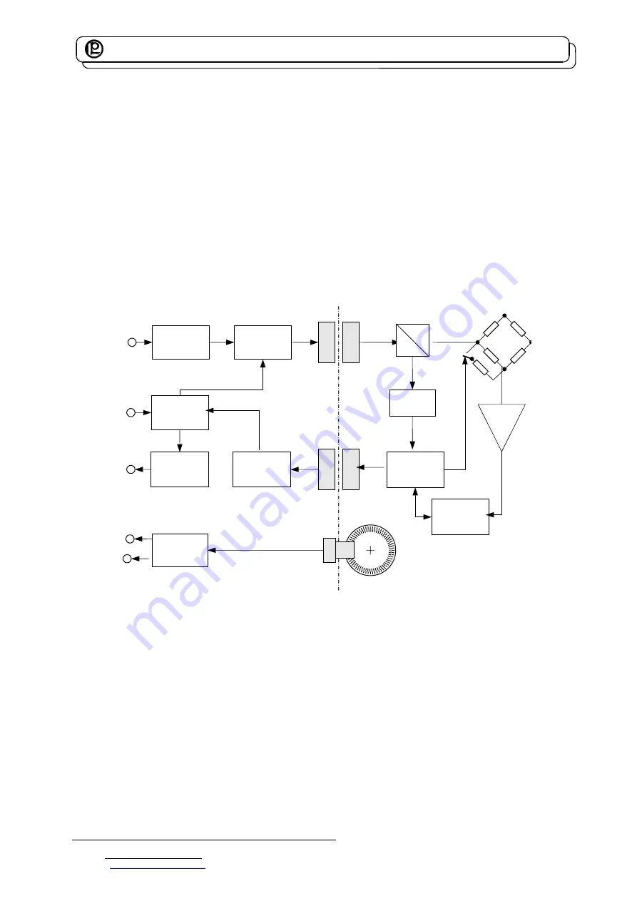
The supply of the rotor electronics occurs by an alternating voltage, generated in the stator, which
transfers to the rotor through a rotating transformer. There, it is rectified and stabilized. With this supply,
the strain gauge bridge is fed.
For the electrical calibration control of the sensor, a control signal is up-modulated to the supply by the µ-
processor in the stator and transferred to the rotor. There, it is filtered and evaluated by the µPC, which
also activates the internal switch for the detuning of the strain gauge bridge.
The measuring signal of the strain gauge bridge is conditioned in an amplifier and then converted into a
digital signal, which will be transferred to the stator by another rotating transformer. Compared to the
analog signal, the measuring signal in digital form is much more disturbance-free. The remaining distance
of the measuring signal within the sensor occurs in digital form, completely. Thus, the measuring system
achieves a high reliability of operation.
This signal is further conditioned in the stator, comes into a µ-processor, then - depending upon sensor
type - it is converted to a voltage signal, digital signal or to current and will then reach the output of the
sensor and can be directly measured at the connector.
DC
/
DC
Oscillator
4
MHz
Signal
Conditioning
Signal Adaption
Analog or Digital
Signal
Conditioning
A/D-Converter
12
bit
µ
-
Processor
µ
-
Processor
Rotation Angle (Option)
SG
Supply
Voltage
Calibration
Control
Signal
Output
Rotation
Angle Output
(
Option
)
Amplifier
Stator
Rotor
Rotating Transformer
Serial Data Transmission
A
B
AC
DC
Filter for
Control Signal
Cycle and
Control Signal
Supply and
Control Signal
Rotating Transformer
Block Diagram for Serial Signal Transmission
3.2.1 Sensors with Analog Output
At this output, the digital signal is converted into DC voltage of ±5 V (option ±10 V), proportionally to the
torque and is available at the connector output.


