Lord MicroStrain Sensing SG-Link-200 Скачать руководство пользователя страница 33

SG-Link®-200 

User Manual


33 


6.2.3 Widgets Options 


The widget configuration menu is different for each type of widget but typically includes sensor or 
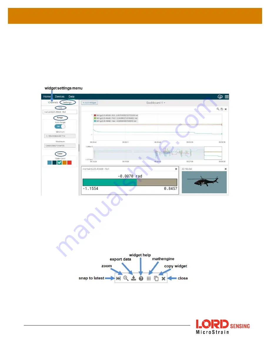
channel selections and widget settings such as titles and legends. 

After adding a widget, left click to select and configure it in the Channels and Settings left sidebar 
menu. Under Channels, the channel(s) for the widget can be enabled and disabled. 


Figure 27 - Widget Settings Menu 


6.2.4 Time Series Widget Menu 


The Time Series Widget menu has two features to help optimize sensor data collection for export to 
a .csv file. 

Snap to Latest 

captures the most recent data and

 Zoom 

isolates specific events from a 

larger data sample (

see Exporting Data Files on page 34

). 


Figure 28 - Time Series Widget Menu 

Содержание Sensing SG-Link-200

Страница 1: ...LORD Sensing USER MANUAL SG Link 200 Wireless Analog Input Node...

Страница 2: ...lliston VT 05495 United Statesof America Phone 802 862 6629 Fax 802 863 4093 9 00 AM to 5 00 PM Eastern Time US Canada http www microstrain com sensing_support LORD com sensing_sales LORD com Document...

Страница 3: ...Discovered On Same Frequency 14 Figure 6 Node On Other Frequency 14 Figure 7 Move Node 15 Figure 8 Add Node By Address 16 Figure 9 Add Node Confirmation 16 Figure 10 Failure to Add Node 17 4 Wireless...

Страница 4: ...aphs 32 6 2 3 Widgets Options 33 Figure 27 Widget Settings Menu 33 6 2 4 Time Series Widget Menu 33 Figure 28 Time Series Widget Menu 33 6 2 5 Exporting Data Files 34 Figure 29 Exporting Data 34 7 Ins...

Страница 5: ...45 c Disposal and Recycling 45 d Radio Specifications 46 11 References 47 http www microstrain com support documentation 47 Product Ordering 48 http www microstrain com wireless 48 Sales Support 48 a...

Страница 6: ...le nodes allows interface with many types of sensors including accelerometers strain gauges pressure transducers load cells torque and vibration sensors magnetometers 4 to 20 mA sensors thermocouples...

Страница 7: ...z Users can easily program nodes for continuous periodic burst and event triggered sampling with SensorConnect Other features of the SG Link 200 include an adjustable PGA digital low pass filter flash...

Страница 8: ...Ohms 6308 4310 Half bridge 350 Ohms 6308 4330 Half bridge 120 Ohms 6308 4320 Quarter bridge 1000 Ohms 6308 4410 Quarter bridge 350 Ohms 6308 4430 Quarter bridge 120 Ohms 6308 4420 U FL interface Full...

Страница 9: ...tus Device status indicator OFF Node is OFF Rapid green flashing on start up Node is booting up 1 slow green pulse per second Node is idle and waiting for a command 1 green blink every 2 seconds Node...

Страница 10: ...e mode When sampling stops the node is switched into idle mode which is used for configuring node settings and allows toggling between sampling and sleeping modes The node will automatically go into t...

Страница 11: ...ctingany hardware Access the free software download on the LORD Sensing website at http www microstrain com software SensorCloud is an optional data collection visualization analysis and remote manage...

Страница 12: ...ed to the gateway through the USB connection Verify the gateway status indicator is illuminated showing the gateway is connected and powered on 2 Open the SensorConnect software 3 The gateway should a...

Страница 13: ...y on Same Frequency If the base and node are on the same operating frequency the node will populate below the Base Station listing when powering on the SG Link 200 Figure 5 Node Discovered On Same Fre...

Страница 14: ...SG Link 200 User Manual 15 Highlight the new node being added and select Move Node to Frequency Figure 7 Move Node...

Страница 15: ...ode manually requires entering the node address and its current frequency setting Figure 8 Add Node By Address If the node was successfully added two confirmation messages will appear and it will be l...

Страница 16: ...ld indicate the node is not in idle mode or it may be on another frequency If Add Node Anyway is selected it will associate that node with the channel entered but it is likely there will be a communic...

Страница 17: ...able settings Figure 11 Hardware Configuration Menu l ExcitationVoltage Setthevoltageofthe SensorPower output Usethehighestvoltage forbestresolution Usethelowestvoltageforlongerbatterylifeandtoreduces...

Страница 18: ...ilterisusedtoreducenoise Setthefiltertoa high frequency for a fast settling time and longest battery life Set the filter to a lower frequency for reduced noise at the costof alongersettlingtime Slower...

Страница 19: ...Analog channels may be independently calibrated with linear calibration coefficients Use the Cal Tools wizard for easy calibration for strain gauges or mV V sensors or output raw units such as volts a...

Страница 20: ...transmitting dataagain l Diagnostic InfoInterval Atthedefinedtransmitinterval thewirelesssensorwillreport diagnostic information The node will continue to transmit this diagnostic information in all o...

Страница 21: ...Internal Temperature Valid range 40 to 125 C sint8 Celsius Low Battery Indicator 0 good 1 low 2 critical sensor will stop sampling uint8 External Power 0 not connected 1 external power connected uint8...

Страница 22: ...ted underDefaultOperationMode thenodewillautomaticallyre enterthesamplemodeit performedlastwithallcurrentsettings DisableUserInactivityTimeouttoavoidthenode automatically changingstates l Check RadioI...

Страница 23: ...f nodes or restarting the last used sampling mode l Single node FromDevices selectNodeaddress Sample ApplyandStartNetwork to begin collectingdata froma singlewirelesssensor Figure 15 Single Node Sampl...

Страница 24: ...ng Using time slots assures the transmissions will not collide or corrupt each other It also provides a means for efficiently scaling the size of the network to allow as much data throughput as possib...

Страница 25: ...calculatedbysquaringthemeanofallmeasurementstakenwithinthewindow and taking the square root l Peak toPeak iscalculatedbysubtractingthesmallestvaluefromthewindowfromthe largest value 5 4 Sampling Opera...

Страница 26: ...SG Link 200 User Manual 26 Figure 19 Event Triggered Sampling...

Страница 27: ...0 User Manual 27 5 5 Output Operation There are three options for managing data acquired from the SG Link 200 The user can transmit collected data log the data to flash memory or do both Figure 20 Dat...

Страница 28: ...to the host computer or SensorCloud SensorCloud is based on cloud computing technology and is designed for long term collecting and preservation of data Features include time series and visualization...

Страница 29: ...m Figure 21 SensorCloud Log in or Register 6 1 2 Navigating Menus The SensorCloud interface has six main views When logging in as a registered user the Device view is the default Navigate to other vie...

Страница 30: ...nables data from any source such as non Ethernet LORD Sensing gateways or third party sensor to be uploaded to the SensorCloud platform The data must be in the LORD Sensing CSV format Data This view i...

Страница 31: ...SG Link 200 User Manual 31 Figure 24 MathEngine View Figure 25 FFT Graph in SensorCloud...

Страница 32: ...reading This format provides an easy way to organize many sensors and networks and it allows the information to be displayed in the most appropriate layout Figure 26 Viewing Data 6 2 2 Navigating Gra...

Страница 33: ...e it in the Channels and Settings left sidebar menu Under Channels the channel s for the widget can be enabled and disabled Figure 27 Widget Settings Menu 6 2 4 Time Series Widget Menu The Time Series...

Страница 34: ...ual 34 6 2 5 Exporting Data Files To export data to a csv file select the Export Data button on the Time Series widget Export name the document save to the preferred location on the host computer Figu...

Страница 35: ...here are 2 clear fit mounting holes on the SG Link 200 for M8 fasteners The node can be mounted in any orientation but it is recommended that it is mounted in a way that optimizes wireless communicati...

Страница 36: ...terfereat thereceiver Generally thehigher abovethegroundthebetter l Minimize Radio Frequency Interference RFI from other wireless devices especially those operating in the same frequency range This in...

Страница 37: ...enu and is highly dependent on the physical environment surrounding the devices 7 1 1 1 Select the node name Range Test Figure 31 Range Test Menu 7 1 1 2 RSSI is a measure of signal strength between t...

Страница 38: ...SG Link 200 User Manual 38 8 Troubleshooting 8 1 Troubleshooting Guide...

Страница 39: ...indicator LED 2 2 node is out of range Perform a bench test with the node in close proximity to the gateway to verify they are operational For range test and installation recommendations See Range Te...

Страница 40: ...t up 4 1 error on startup Power down node for 10 seconds and repower 4 2 low power Replace battery or power source and repower node 4 3 node is damaged If Red LED persists after all power settings and...

Страница 41: ...re to the most current version Updates are found on the LORD Sensing website product page under the Downloadstab 1 Download the Firmware Upgrade file from the LORD Sensing website product page under t...

Страница 42: ...tem by LORD Sensing Warranty Repairs LORD Sensing warrants its products to be free from defective materialand workmanship for a period of one 1 year from the original date of purchase LORD Sensing wil...

Страница 43: ...SG Link 200 User Manual 43 9 Specifications a Physical Specifications Dimensions 41 3 mm x 29 mm x 5 9 mm Weight 235 grams 326 grams w battery...

Страница 44: ...SG Link 200 User Manual 44 b Operating Specifications...

Страница 45: ...housing to protect it from environmental elements impact and electrostatic discharge ESD which can disrupt operation or damagePCB c Disposal and Recycling The SG Link 200 contains printed circuit boa...

Страница 46: ...less communication The radio is a direct sequence spread spectrum radio and can be configured to operate on 16 separate frequencies ranging from 2 405 GHz to 2 480 GHz Following the 802 15 4 standard...

Страница 47: ...pport documentation For further assistance our technical support engineers are available to help with technical and applications questions Technical Support sensing_support LORD com Phone 802 862 6629...

Страница 48: ...ng website including product user manuals technical notes and quick start guides These documents are continuously updated and new applications are added They may provide more accurate information than...

Страница 49: ...how it is set up for data acquisition It includes settings such as sampling mode rate number of active channels channel measurement settings offsets hardware gain and calibration values Continuous Sam...

Страница 50: ...ceiving antennas in a radio network As stated it means the antennae are in view of each other with no obstructions LXRS Lossless Extended Range Synchronized is the proprietary LORD Sensing data commun...

Страница 51: ...onditions producing apredictable electrical signal Sleep a command transmitted to the node to put it into sleep configuration Sampling the process of taking measurements from a sensor or device Sampli...

Страница 52: ...packets second Transmission window the time allowed for one data transmission at the automatically determined transmission rate USB Universal Serial Bus is a serial data communications protocol WSN W...

Отзывы: