background image

3DM-CX5-GNSS/INS 

User Manual


3.1


Software Installation 


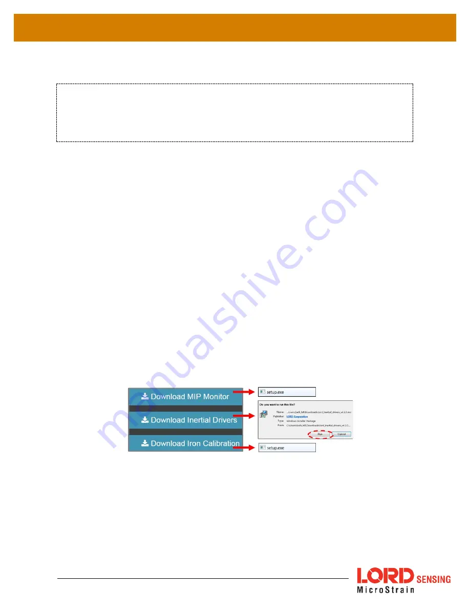
To Install the MIP Monitor software on the host computer, complete the following steps: 


1.


Launch the MIP Monitor software installation menu at:


https://www.microstrain.com/software

. 


2.


Download and open the MIP Monitor .zip file. 


3.


Run the setup.exe file, and follow the on-screen prompts to completion. 


4.


Download and open the Inertial Drivers zip folder to install the hardware drivers required 
for operating the sensor. 


5.


Run the .msi file, and follow the on-screen prompts to completion. 


6.


Download and open the Iron Calibration .zip file to facilitate magnetometer field 
calibration. 


7.


Run the setup.exe file, and follow the on-screen prompts to completion. If prompted, 
reboot the computer when complete. 


Figure 4.  Software Installation Menu


NOTE 

The MIP Monitor Software Suite includes hardware drivers required for 3DM-CX5-45 sensor 
operation.  Sensors will not be recognized without these drivers installed. 

Содержание 3DM-CX5 Series

Страница 1: ...3DM CX5 GNSS INS GNSS Aided Inertial Navigation System LORD USER MANUAL...

Страница 2: ...icane Lane Williston VT 05495 United States of America Phone 802 862 6629 www microstrain com sensing_support LORD com sensing_sales LORD com Copyright 2019 LORD Corporation Document 8500 0084 Revisio...

Страница 3: ...elp Menu 9 3 4 Sensor Communication 9 3 5 GNSS Satellite Link 11 3 6 Sensor Settings 11 3 6 1 Saving Configurations 12 3 7 Data Monitoringand Recording 13 3 8 View Recorded Data 14 4 Sensor Measuremen...

Страница 4: ...ag Adaptive 36 5 8 Angular Rate andAcceleration Limits 37 5 9 Communications Bandwidth 37 5 10 Platform Frame Transformation 37 5 11 Estimation Filter Operation 37 5 12 Estimation Filter Convergence 3...

Страница 5: ...de 49 8 2 Repair and Calibration 53 8 3 Maintenance 53 8 4 Technical Support 54 9 Parts and Configurations 55 9 1 Standard Configurations 55 9 2 Accessories 57 9 3 Sales Support 57 10 Specifications 5...

Страница 6: ...bias tracking auto zero update options ZUPT and user adjustable sensor noise factors All sensors are fully temperature compensated and calibrated over the full operating temperature range The use of...

Страница 7: ...ntal compensation and dual on board processing with an Auto Adaptive Extended Kalman Filter EKF allows the 3DM CX5 GNSS INS to perform well in a wide varietyof applicationsthat require low noise drift...

Страница 8: ...ordering information Item Description Model LORD Sensing Part Number A 3DM CX5 GNSS INS Inertial Sensor GNSS INS 8G 300 DPS 6271 4260 MIP Monitor Software Suite http www microstrain com software For a...

Страница 9: ...clude a device status indicator and the device information label The tablebelow describesthebasicstatusindicatorbehavior Thedeviceinformationlabelincludes the sensor frame diagram axis orientation whi...

Страница 10: ...the application MIP Monitor includes a message building tool that can be used to streamline this process For more information see OEM System Integration on page 51 In this section hardware and softwar...

Страница 11: ...Inertial Drivers zip folder to install the hardware drivers required for operating thesensor 5 Run the msi file and follow the on screen prompts to completion 6 Download and open the Iron Calibration...

Страница 12: ...netic antenna adapter cable and a host computer with LORD Sensing MIP Monitor installed Figure 5 System Connections Power is applied to the sensor through an external power supply such as the one prov...

Страница 13: ...enu is available by right clicking on the device name and includes the most used items from the header row menus The header row menu includes selections for data sampling recording device settings ope...

Страница 14: ...cts the appropriate serial communication USB or TTL on power up based on which cable is connected If the hardware drivers have been installed communication can be established using the MIP Monitor sof...

Страница 15: ...ot actively being exchanged between the sensor and host computer the status message may display Not Connected This indicates the port status not the sensor availability When commands are sent to the s...

Страница 16: ...n the sensor name highlighted in the main window and then select Device Settings or select Settings Device from the main menu a Main menu tabs The main tabs divide the settings into functionalgroups f...

Страница 17: ...ed the next time the device is powered on select Settings Save Current Settings First adjust the sensor settings to the desired values Next select Settings Save Current Settings from the main window F...

Страница 18: ...nd recording Each view corresponds to one of the main categories in the Device Settings window For example the 3DM CX5 GNSS INS includes Sensor Data Monitoring for the IMU AHRS measurements GNSS Monit...

Страница 19: ...e MIP Monitor software main window and select Sensor Data Monitor 2 Click the blue Start Streaming icon to start sampling 3 8 View Recorded Data Figure 12 Data Streaming Recorded data is stored in eit...

Страница 20: ...option This settings file is the same as selecting Export Settings from the Settings menu Figure 13 Data Recording 4 To end recording press the Arm Recording button and select OK in the confirmation...

Страница 21: ...elocity change in velocity Temperature and pressure sensors provide environmental information for measurement compensation and altitude estimations GNSS information can be read directly and is also us...

Страница 22: ...malies All measurements are temperature compensated and are mathematically aligned to an orthogonal coordinate system The IMU sensors can be read directly to report stand alone inertial measurements o...

Страница 23: ...three axis acceleration readings in engineering units Magnetic Field Gauss G three axis magnetic field readings in engineering units Angular Rate radian second three axis rotational velocity reading f...

Страница 24: ...outputs In the MIP Monitor software there are user settable options for how the estimations are made These settings are available at Settings Device EF With the Help window open accessed with the Help...

Страница 25: ...ertainly estimation available Acceleration Linear and Compensated meter second2 absolute or linear acceleration readings with reference to either the sensor or vehicle frame depending on settings with...

Страница 26: ...latitude longitude and height h above the reference ellipsoid Latitude ranges from 90 degrees at the South Pole to 90 degrees at the North Pole Longitude ranges from 180 to 180 degrees with 0 degrees...

Страница 27: ...st vector along the line of latitude and the Down vector normal to and towards the tangent plane Figure 18 North East Down Frame The assumption when using the NED frame is that the local surface can b...

Страница 28: ...l sensor biases and corrections in this frame When no sensor to platform frame transformation has been provided see Platform Frame on page 32 The orientation of the sensor frame with respect to the lo...

Страница 29: ...respect to the origin of the sensor frame expressed in the sensor frame In the following example the user has defined the desired reference point on the platform frame to be located at the front bumpe...

Страница 30: ...d acceleration compensated angular rate and gravity vector It also affects the following IMU outputs acceleration angular rate magnetic field vector delta Theta and delta velocity see Computed Outputs...

Страница 31: ...To set the gyroscope baseline place the sensor or sensor platform in the desired home position Allow 2 3 minutes for the sensor to warm up and for the temperature to stabilize for the best bias captu...

Страница 32: ...orresponding LORD Sensing MIP Data Communications Protocol DCP command see the DCP Manual To tare the pitch roll select the sensor name in the MIP Monitor software main window then select Settings Tar...

Страница 33: ...on of the magnetometer scale factor scale factor tracking for purposes of auto calibration To enable select the sensor name in the MIP Monitor software main window then select Settings Device Estimati...

Страница 34: ...bration software which is included in the MIP Monitor software suite see Software Installation on page 12 This command also resets the auto calibration coefficients The Capture command should only be...

Страница 35: ...sources are hard to avoid or arehidden Tomitigatethiseffectwhenusingthe3DM CX5 GNSS INSmagnetometertoaidinheadingestimations a field calibration of the magnetometer after final installation is highly...

Страница 36: ...ic sources such as driving over railroad tracks or near steel pilings The intention is to get a baseline of the platform in a neutral environment that still accounts for the platform itself in all ori...

Страница 37: ...n use the Refresh button if needed to re establish communication with the sensor 9 Start a calibration verification by clicking the Start Streaming Data button next to Verify Calibration Figure 28 Ver...

Страница 38: ...e has three optionsincluding None InternalGNSS and External GNSS Message see GPS External Receiver on page 1 2 Heading Aiding has eight options including None1 None 2 Magnetometer 3 GNSS velo city 4 E...

Страница 39: ...y are sensed e g when stationary or traveling in the same direction at a constant velocity If using velocity as a heading reference the sensor or sensor platform has to be moving or there will be no h...

Страница 40: ...gation run 5 7 Adaptive Anomaly Rejection 5 7 1 Gravity Adaptive Enabling this feature allows the filter to stabilize attitude readings when undergoing linear accelerations The bandwidth setting deter...

Страница 41: ...o find this setting select the sensor name and then Settings Device Estimation Filter Mag Adaptive Manual Adaptive default setting Enter user set fixed values Auto Adaptive Automatically estimates the...

Страница 42: ...ccomplish this is to co align the frames If this is not possible using a simple transformation such as 90 or 180 degree rotations on a single axis is preferred For complex transformations between the...

Страница 43: ...rge errors in the heading estimation Transient errors can be suppressed when the magnetometer readings are combined with information from the gyroscopes but only for periods on the order of a few seco...

Страница 44: ...aking thesensoreasier to deploy The Kalman filter also provides statistical information about the quality of the estimated states described in a covariance matrix The diagonal terms of the matrix are...

Страница 45: ...rnal sensors in the 3DM CX5 GNSS INS are calibrated when the device is manufactured and the calibration values are saved in the device memory With the exception of the magnetometer field calibration s...

Страница 46: ...name in the MIP Monitor software main window then select Settings Export Settings then follow the prompt to choose where the file will be saved and select OK The file will be named by default using th...

Страница 47: ...two mounting tabs with holes for fastening Mounting screws should be brass or 300 Series stainless steel Nylon washers and thread lock are recommended There are two additional holes used for precise a...

Страница 48: ...ata output format The commands and data are divided into four command sets and three data sets corresponding to the internal architecture of the device The protocol is packet based All commands replie...

Страница 49: ...in the Standard communications mode to use this feature Figure 35 Packet Builder 7 1 2 Sensor Direct Mode The MIP Monitor software can be used to put the sensor in a mode that allows direct programmat...

Страница 50: ...onitor main window Once in this mode the device status message will indicate Sensor Direct Mode Figure 36 Sensor DirectMode To exit Sensor Direct Mode select the Refresh button in the MIP Monitor at a...

Страница 51: ...ction is used Figure 37 Pin Locations and Functions Pin Number Net Name Function 1 USBDM USB DATA 2 USBDP USB DATA 3 Vin Power Supply 4 RxD UART receive host to CV5 5 TxD UART transmit CV5 to host 6 G...

Страница 52: ...u select 3DM CX5 45 and then select document from the list To save the current sensor configuration first adjust the sensor settings to the desired values and then start streaming Next select Settings...

Страница 53: ...Support on page 62 7 5 Using Wireless Adapters In some applications it can be very useful to set up wireless communications between the sensor to the host computer One way this can be accomplished is...

Страница 54: ...3DM CX5 GNSS INS User Manual 49 8 Troubleshooting 8 1 Troubleshooting Guide...

Страница 55: ...l Support on page 62 2 1 sensor not found in MIP Monitor 2 COMMUNICATION no communication to In MIP Monitor use the Refresh button to look for the sensor again If the sensor is still not found try cyc...

Страница 56: ...ed or recorded enter the Device Settings menu and verify the sampling settings 3 2 streaming has not started If data streaming is occurring the sensor device status indicator will also be flashing to...

Страница 57: ...isrupt the sensor operation and cause magnetization of internal components which can affect magnetometer performance If magnetization is suspected use a degaussing tool to demagnetize 3 7 sensor is da...

Страница 58: ...from defective material and workmanship for a period of one 1 year from the original date of purchase LORD Sensing will repair or replace at its discretion a defective product if returned to LORD Sen...

Страница 59: ...FAQs and product manuals http www microstrain com support_overview aspx For further assistance our technical support engineers are available to help with technical and applications questions Technica...

Страница 60: ...he LORD Sensing Sales Department Table 4 Model Numbers describes the standard models available at the time this manual was published Once a model is selected the part number is further defined by desi...

Страница 61: ...Manual 56 The same options are available in each model and are indicated in the last four digits of the product part number For a list of the starter kit contents see Components on page 1 Figure 39 S...

Страница 62: ...tions cable 9022 0019 GNSS dual feed antenna with 3m cable SMA connector 9010 0150 Antenna cable adapter MMCX to SMA 9022 0032 Sensor mating connector micro DB9 with flying leads 6224 0100 Table 5 Sen...

Страница 63: ...3DM CX5 GNSS INS User Manual 58 10 Specifications See Datasheet for Specifications https www microstrain com inertial sensors 3DM CX5 GNSS INS...

Страница 64: ...product installation and troubleshooting For more information contact LORD Sensing Technical Support see Technical Support on page 62 11 1 Sensor Dimensions and Origin This diagram describes the sens...

Страница 65: ...CX5 GNSS INS User Manual 60 11 2 GNSS Antenna Specifications These specifications describe the GNSS antenna included in the 3DM CX5 GNSS INS connectivity kit as well as the short sensor to SMA coax ju...

Страница 66: ...User Manual 61 11 3 Power Supply Specifications RS232 kits only The power supply is only required for the RS232 devices These specifications describe the power supply included in the 3DM CX5 GNSS INS...

Страница 67: ...d Power Cables These diagrams describe the cables included in the 3DM CX5 GNSS INS connectivity kits Only one is included in each kit depending on the type of kit ordered Figure 41 RS232 Communication...

Страница 68: ...o wire from MicroStrain s standard connector to their own equipment Pin Signal Color 1 D usb Black 2 D usb Brown 3 V Red 4 RX rs232 Orange 5 TX rs232 Yellow 6 V Green 7 Blue 8 GND Violet 9 Grey Figure...

Страница 69: ...se documents are continuously updated and may provide more accurate information than printed or file copies Document Where to find it 3DM CX5 GNSS INS support documentation http www microstrain com do...

Отзывы: