


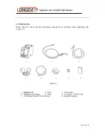


MigWeld 140 140 AMP MIG Welder
Page
20
of
27
6
Figure C-3
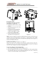
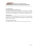
3.
Tighten the wing screw
○
3
attached to the connector block of the wire feed gearbox.
4. Make sure the Gun changing switc
h
○
7
is in the correct position MIG for standard
welding and Spool Gun if optional gun is installed.
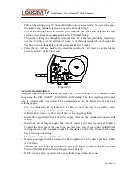
Wire Drive Roll Installation
(See Figure C-4)
The reversible dual groove wire drive roll
attached to MigWeld140 has two wire grooves;
One for .025” (0.6mm) solid welding
wire and the other for .030-.035” (0.8-0.9mm)
solid or flux-cored welding wire. The
factory default installation is .025” (0.6mm)
.
In the event that .030” (0.8mm) - .035”
(0.9mm) welding wires are used, the wire feed
roll groove must be changed.
1.
Ensure that the MigWeld 140 welding machine is
powered off.
2.
Unlatch the spring loaded pressure arm and Figure C-4
open the idle roll arm.
○
1
and lift up the idle
roll arm.
○
2
3.
Loosen the hex bolt
○
3
that attaches the wire drive roll.
4.
Remove the wire drive roll
○
4
and flip the wire drive roll over so that the .030” (0.8mm)
mark faces the user.
5.
Reinstall by putting back the wire drive roll and tighten the hex bolt.
4
3
1
2
7
Figure C-2
3
4
Содержание MigWeld 140
Страница 25: ...MigWeld 140 140AMP MIG Welder Page 25 of 27 ...