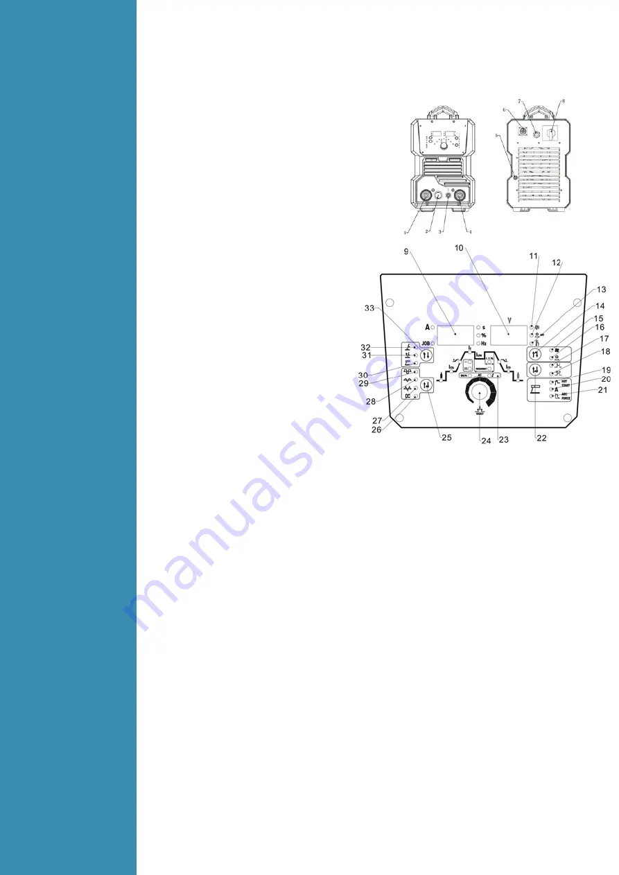
(
1
)
“-” Output terminal.
(
2
)
TIG torch remote connection socket. *
(
3
)
TIG torch gas connector.
(
4
)
“+” Output terminal.
(
5
)
Inlet gas connector.
(
6
)
Water cooler remote connection socket.
(
7
)
Input power cable.
(
8
)
Power switch Control Panel
(
9
)
LH multifunction display.*
(
10
)
RH multifunction display.*
(
11
)
Power indicator .
(
12
)
Water cooling system error indicator.*
(
13
)
Alarm indicator. *
(
14
)
Water /air cooling selection button.*
(
15
)
Air cooling mode indicator
(
16
)
Water cooling mode indicator
(
17
)
2T trigger mode indicator. *
(
18
)
4T trigger mode indicator. *
(
19
)
MMA hot start setting Indicator. *
(
20
)
MMA welding current setting Indicator.
(
21
)
MMA arc force setting Indicator. *
(
22
)
2T/4Ttrigger mode selector button
(
23
)
TIG parameter setting indicator. *
(
24
)
Parameter select/adjust Knob. *
(
25
)
Welding current mode selection button
(
26
)
DC wave output indicator. *
(
27
)
AC triangle wave output indicator. *
(
28
)
AC sine wave output indicator. *
(
29
)
AC advanced square wave output indicator. *
(
30
)
MMA mode indicator
.
(
31
)
Lift TIG mode indicator. *
(
32
)
Hf TIG mode indicator. *
(
33
)
Welding mode selection button
*Denotes more detailed explanation of function to follow.
Further Controls Explained
LH Digital Multifunction Display (9)
Before welding this displays the setting selected or being adjusted using the control knob (24). During
welding it displays welding current. The parameter setting displayed is indicated by the LEDs beside
the display; Current (A), Saved Setting (JOB), Time (S), Percentage (%) and Frequency (Hz). If left
inactive for several seconds, display will revert back to main welding current setting.
RH Digital Multifunction Display (10)
Before welding this displays secondary functions and error codes. During welding it displays welding
voltage.
Multifunction Smart Control Knob (24)
Press knob to navigate through the control panel parameters not controlled by specific selector
buttons. Parameter/setting selected will be indicated by the LED on the control panel and the value
shown on the LH display (9). Adjust the parameter by turning the knob. Access the job/program
store/ recall function by pressing and holding the knob.
Water Cooling System Error Indicator (12)
When using the integrated water cooler, the system is equipped with a pressure sensor. If the coolant
pressure is insufficient, this indicator will light and the welding output will not be able to be active, in
order to protect the torch and cooling system.
Alarm Indicator (13)
Lights when over voltage, over current, input phase loss or electrical overheating (due to exceeding
duty cycle) is detected and protection is activated. When protection is activated, welding output will
be disabled until the safety system senses the overload has reduced sufficiently and indicator lamp
goes out. May also trigger if machine experiences an internal power circuit failure.
3
Installation
&
Operation
3.1
Layout for
the front
and rear
panel
Содержание Grand Tig 400 ACDC Pulse
Страница 24: ...4 4 Electrical schematic drawing...


