1
SETUP AND INSTALLATION
SETUP
Installation Manual
Page
13
© Logic Energy Ltd. Registered in Scotland
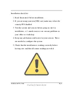
2.5 Installation Checklist
Before powering up the LeNETmobile device, check that the installation is correct. Following is the quick
checklist for installation:
1.
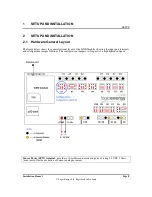
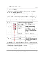
Make sure the sensors connections are sound and the jumpers are configured correctly for each
port connected to signal source/sensor.
2.
For wind applications, the primary/top anemometer must be connected to port A1 and the
primary/top wind vane must be connected to port D5.
3.
An active GSM (Cellular) SIM is inserted in the GSM module. Also make sure the antenna is
connected to the module. If using an external antenna, ensure it is securely mounted, and not
obstructed by metal enclosures or masts and preferable vertical position.
4.
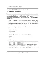
If you are using your own SIM, then make sure that micro-SD card contains the correct GPRS
settings in the configuration file.
5.
Power up the device using appropriate powering source.
Note:
Once the system is in operation, check that the device communicates with the server, and that the
server shows new data each measurement interval. Also check that data makes sense before leaving the
installation site.
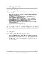
2.6 LEDs Status
There are two LEDs on LeNETmobile to indicate its operating state. They are:
•
Activity LED
(GREEN LED-gear wheel symbol) blinks every 1 second (or few seconds) during
normal operation of the system, while the other LED stays OFF. This LED also indicates memory
card access.
•
GSM LED
(AMBER LED-antenna symbol) flashes during the communication cycle only, while
the other LED stays OFF.

