If your signal is an “absolute” type (that means it has two red LEDs for the stop position while all others are yellow) then you
will have to cut the exposed lead on the diode D4 shown in Figure 5 above on the Signal Animator board. Use a pair of
diagonal cutters to make the cut. Be sure that the two cut ends no longer touch each other by separating them slightly. Failure
to do so won’t cause any damage but it may cause the center yellow LED to illuminate when the signal is in the stop position.
Mounting and wiring the IR components
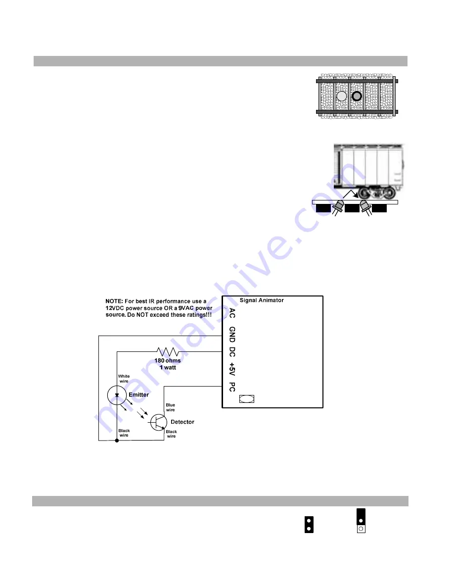
The IR components should be mounted between the rails. Drill two 11/64” holes,
through the ballast, roadbed, and sub-roadbed. These holes should be located one tie
apart (Figure 7a) and drilled at approximately a 45 to 60 degree angle from horizontal as
illustrated in the side view in Figure 7b. The benefit of mounting them at an angle is
reduced false triggering from overhead light and increased detection reliability in smaller
scales or irregular bottoms on rolling stock. For the smaller scales this drilling may end
up hitting the ties. Take your time so you don’t mangle them! Insert the leads of one IR
emitter (white and black wires) into one of the holes (it doesn’t matter which one!) from
the top of your layout. Repeat for the IR detector (blue and black wires). The tops of the
components should sit no higher than the top of your ballast for optimal IR performance;
in some cases (e.g. false triggering) it may be necessary to locate the components a little
below the ballast line. You can extend the leads with similar (or larger) wire. We
recommend soldering and insulating these connections. We also recommend using
terminal blocks/strips since you’ll have multiple DC and GND connections to make.
Once you have wired the IR components and verified their operation you may wish to
put a dab of white glue or silicone caulk where the wires exit the holes underneath the
layout. This will help to hold the components in place; make sure you don't get any
substance (e.g. ballast or glue) on the top surface of the IR components as this may
prevent them from operating properly. In extreme cases where you may be getting
interference from overhead lighting you can mount the IR detector in some plastic or
metal tubing. You can also recess the IR detector slightly below the ties and roadbed.
Figure 4a
Figure 4b
Figure 8 illustrates the wiring for the IR components. The 180 ohm 1 Watt resistor is included with the
Signal Animator
.
WARNING: The 180 ohm 1 watt resistor may become hot to the touch – take care so that you don’t burn yourself!
When properly wired the emitter will have a very faint red glow coming from it. You can also look at the emitter through a
digital camera and see the infrared light!
For safety reasons do NOT point the IR emitter directly into your eye or stare at the
IR emitter!!!
Figure 8 – IR component wiring
You can adjust the sensitivity of the IR detector by inserting a small screwdriver in the component labeled "VR1". Turning
the screwdriver clockwise will increase its sensitivity. With a piece of rolling stock covering the sensor turn the VR1 fully
counter-clockwise and then slowly clockwise until the signal changes to red. Then slightly turn the screwdriver a little more
clockwise. Move the rolling stock away from the sensor and verify proper signal operation (delay, yellow, delay, green).
Signal delay
The signal color change delay can be either 10 seconds or 30 seconds. Choose the value
based on your own personal preference. To select 10 seconds the jumper must be
installed over both pins on the block "DLY"; for 30 seconds the jumper must only cover
one pin (it doesn't matter which one). You can change this as you wish even when the
power to the Signal Animator is on. The two options are illustrated in Figure 9.
DLY
10 seconds
DLY
30 seconds
Figure 9 – signal delay


