ZOOM OMAP35x DevKit
12
QuickStart Guide
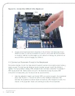
Figure 2.6 – Connect the SOM-LV to the Baseboard
3.
Visually verify that the socket connectors on the SOM-LV and baseboard have
mated correctly. To remove the SOM-LV, pull up on the board above the socket
connectors. Attempt to pull straight up and refrain from flexing the printed circuit
board (PCB) to avoid damaging the SOM-LV.
2.4 Connect an Expansion Board to the Baseboard
This section applies to both the high-density breakout board and the high-precision analog
adapter board. The high-density breakout board provides access to all of the SOM-LV
signals. The high-precision analog (HPA) adapter board provides connectors to evaluate TI
HPA development kits. Both boards connect to the baseboard using the same BTB
connectors; consequently, only one board can be used at a time.
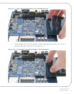
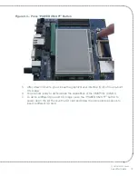
1.
Align the expansion board over the two BTB connectors closest to the baseboard
edge. See Figure 2.7. (There is an outline on the baseboard silkscreen that
specifies the expansion breakout board connectors). When aligned correctly, the
majority of the expansion board will overhang the side of the baseboard.
Содержание Zoom Torpedo OMAP35 Series
Страница 1: ...Z O O M QuickStart Guide www logicpd com OMAP35x Development Kit...
Страница 2: ......
Страница 3: ...ZOOM OMAP35x DevKit QuickStart Guide We fast forward the evolution of new products...
Страница 33: ......


