background image

ZOOM OMAP35x DevKit

22

QuickStart Guide

3.

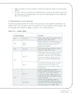
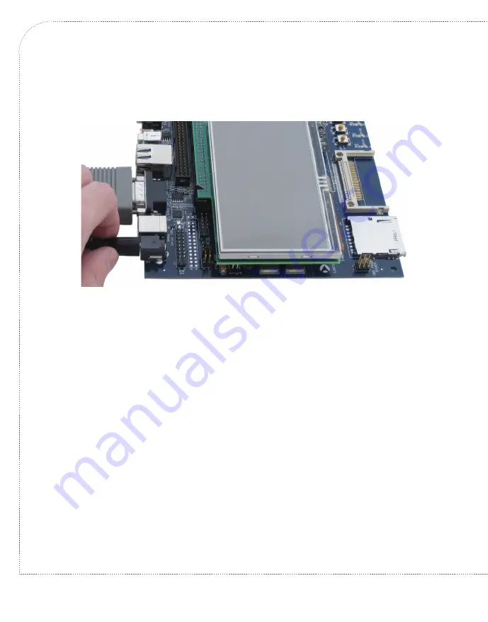
Connect the regulated 5V power supply to the appropriate power adapter for the 
location in which you are using the development kit.

4.

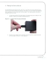
Plug the power adapter into an electrical outlet and the 5V line output connector 
into the power-in connector on the baseboard.

Figure 4.3 –  Connect Power to Baseboard

5.

Before powering on your kit, you will have to install a terminal emulation program to 
communicate with the development kit. Please proceed to the next section for 
details.

4.3 Terminal Emulation Installation

The Zoom OMAP35x Development Kit is designed to communicate with terminal emulation 
programs using the included null-modem serial cable. The terminal emulation program must 
support binary transfers in order to download software to the kit. Although Logic does not 
support any particular terminal emulation program, we suggest using Tera Term Pro for 
Windows 2000 or XP (Tera Term Pro is not available for Linux users). Tera Term Pro can be 
downloaded for free from Logic’s website. To install Tera Term:

1.

Download the.zip file from Logic’s website and unzip the contents:


www.logicpd.com/downloads/240/

2.

After unzipping the contents, locate the “setup.exe” file and double-click it. 

3.

Follow the on-screen instructions to install Tera Term.

Once the terminal emulation program has been installed on your PC, open a new serial port 
connection using the COM port where the null-modem serial cable is connected to the host 
PC. Set the ‘baud-rate’ to 115200, ‘data’ to 8-bit, ‘parity’ to none, ‘stop’ to 1-bit, and ‘flow 
control’ to none. (

Hint:

 In Tera Term, you can save these serial port settings by selecting 

Содержание Zoom Torpedo OMAP35 Series

Страница 1: ...Z O O M QuickStart Guide www logicpd com OMAP35x Development Kit...

Страница 2: ......

Страница 3: ...ZOOM OMAP35x DevKit QuickStart Guide We fast forward the evolution of new products...

Страница 4: ...the Baseboard 12 2 5 Connect LCD to Baseboard 14 2 6 Baseboard Jumper Settings 15 3 Ready for Demo Mode 17 4 Ready for Development Work 20 4 1 Register your Development Kit 20 4 2 Connect Development...

Страница 5: ...ard over the Baseboard 13 Figure 2 8 Connect the Expansion Board to the Baseboard 13 Figure 2 9 Connect LCD to Baseboard 14 Figure 2 11 Baseboard JTAG Settings for the OMAP35x SOM LV 16 Figure 3 1 Con...

Страница 6: ...e Expansion and Adapter Boards High density breakout board High precision analog HPA adapter board Embedded Trace Macrocell ETM adapter board Display 4 3 WQVGA TFT LCD with touchscreen SD Memory Card...

Страница 7: ...SD card s SOM LV Regulated 5 volt Power Supply Null modem Serial Cable Ethernet Crossover Cable Application Baseboard Power Adapters Only US cord shown High Density Breakout Board High Precision Analo...

Страница 8: ...ZOOM OMAP35x DevKit 6 QuickStart Guide 1 3 Baseboard Connection Diagram Figure 1 2 Connection Diagram for the Baseboard B A C D E F G I K L M N J U V H O P Q R S T W X Y Z AA AB AC...

Страница 9: ...connector power P 240 pin BTB socket connectors for OMAP35x SOM LV Q 240 pin BTB socket connectors for high density breakout board and HPA adapter board R System reset button S System wake up button T...

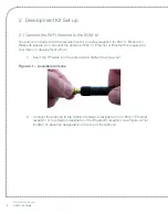
Страница 10: ...y connect the antenna if 802 11 Ethernet or Bluetooth is required for your demo or development efforts 1 Insert the RF cable into the antenna and tighten the screw nut Figure 2 1 Assemble Antenna 2 Co...

Страница 11: ...d trace features for the ARM processor Only connect the ETM adapter board if you need to debug the SOM LV using an ETM interface external debug tool 1 Position the SOM LV so that the Logic logo is to...

Страница 12: ...connectors to mate the two boards See Figure 2 4 for final position of the connected ETM adapter board to the SOM LV Figure 2 4 ETM Adapter Board Connected to SOM LV 2 3 Connect the SOM LV to the Bas...

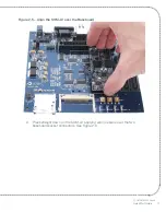
Страница 13: ...OOM OMAP35x DevKit QuickStart Guide 11 Figure 2 5 Align the SOM LV over the Baseboard 2 Press straight down on the SOM LV applying even pressure over the two baseboard socket connectors See Figure 2 6...

Страница 14: ...breakout board and the high precision analog adapter board The high density breakout board provides access to all of the SOM LV signals The high precision analog HPA adapter board provides connectors...

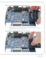
Страница 15: ...3 Figure 2 7 Align the Expansion Board over the Baseboard 2 Press straight down on the expansion board applying even pressure over the two baseboard socket connectors See Figure 2 8 Figure 2 8 Connect...

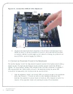
Страница 16: ...adapter board Only one board can be connected at a time 2 5 Connect LCD to Baseboard The 4 3 WQVGA LCD included with the development kit connects to the baseboard 60 pin LCD connector 1 Align the con...

Страница 17: ...mp 1 Jmp 2 Normal operation An individual jumper is placed on each pin and not connected to another pin See Figure 2 11 for a graphical description JP3 Jmp 2 3 ATA Operating Voltageb Default is when j...

Страница 18: ...ard JTAG jumpers JP2 are set for normal operation with the OMAP35x SOM LV as shown in Figure 2 11 below Note For the OMAP35x SOM LV the jumpers should remain in the same position for both normal and J...

Страница 19: ...lities of the development kit for the specific operating system The following steps will walk you through the set up process 1 Connect the regulated 5V power supply to the appropriate power adapter fo...

Страница 20: ...QuickStart Guide Figure 3 2 Connect Power to the Baseboard 3 Insert the SD card into the SD card slot on the baseboard Figure 3 3 Insert SD Card 4 Press the POWER ON OFF button on the baseboard to bo...

Страница 21: ...the graphical user interface GUI of the pre built OS image 6 You are now ready to demonstrate the capabilities of the OMAP35x SOM LV 7 To demo a different pre built OS image press the POWER ON OFF bu...

Страница 22: ...click the Submit button 3 You will receive an e mail with a URL link to confirm account creation Click on the link to finalize account creation 4 You will be directed to a page on Logic s website tha...

Страница 23: ...with an FTDI virtual COM port VCP chip that causes the USB device to appear to your computer as an additional COM port Settings for the terminal emulation program will remain the same however a driver...

Страница 24: ...am must support binary transfers in order to download software to the kit Although Logic does not support any particular terminal emulation program we suggest using Tera Term Pro for Windows 2000 or X...

Страница 25: ...e commands load operating systems configure hardware platforms bring up hardware customize applications perform tests and manage in field devices 1 Make sure the development kit is set up as described...

Страница 26: ...what is shown below Figure 4 6 LogicLoader losh Prompt 7 You are now ready to work with the OMAP35x SOM LV using LogicLoader For information on how to load pre built images as well as build custom Lin...

Страница 27: ...tion provided by Logic These documents are available on the Logic website OMAP35x SOM LV LogicLoader Labs www logicpd com downloads 1096 LogicLoader User Manual www logicpd com downloads 1094 LogicLoa...

Страница 28: ...ts of these directives or other related directives ESD The user assumes all responsibility and liability for proper and safe handling of the goods Further the user indemnifies TI and Logic from all cl...

Страница 29: ...products devkit ti zoom_omap3_development_kit www logicpd com products som ti omap35x 6 1 Optional Zoom Display Kits Zoom Display Kits are ideal for embedded solutions requiring a graphical user inter...

Страница 30: ...ax and BOM pdf Zoom OMAP35x Development Kit QuickStart Guide Zoom OMAP35x Development Kit User Manual OMAP35x SOM LV Hardware Specification White Papers Application Notes and Product Change Notificati...

Страница 31: ...for complete descriptions prices and purchase options Product Development Services Logic offers product development and manufacturing services from initial product concept and design to volume produc...

Страница 32: ...13 08 B PN 1010324 JCA Section 1 1 Updated SD Memory Card listing Section 2 1 Updated instructions for antenna connectors that were moved to top of SOM LV Updated Figure 2 2 Section 2 6 Corrected JP2...

Страница 33: ......
Страница 34: ...nt reserves the right to change devices or specifications detailed herein at any time without notice and does not make any commitment to update the information contained herein The names of the sample...

Отзывы: