background image


RTCU NX-900 Technical Manual V1.02 

Advanced M2M/IIoT Gateway 


Logic IO ApS. 


Ph:   (+45) 7625 0210 

Holmboes Allé 14 


Fax: (+45) 7625 0211 

8700 Horsens                               

Page 27 of 45 

Email[email protected] 

Denmark                                       


www.logicio.com 

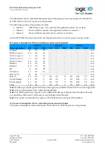
12V/24V DC-Out 

When using the jumper JP101 either 12V or 24 DC is available on the DC-out terminal. The 12V DC 
output can supply a maximum of 500 mA and the 24V DC output can supply a maximum of 250 
mA. The DC-Out is available on the top row of the stacked terminals. This output is named 
boardDCOut2 in the RTCU online help. 
 
The 12V DC-out requires a DC supply voltage of minimum 14 VDC or AC supply to be present 
and the 24V DC-out voltage requires that the AC supply is present. 
 
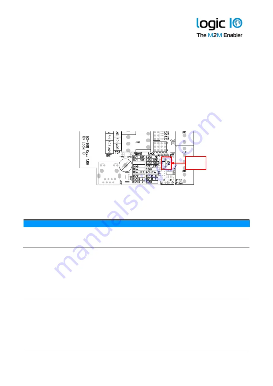
The jumper that switches the DC-out voltage level between 12V DC and 24V DC is located front of 
the communication terminal rows as shown below: 


DC-Out terminals 
Terminal Name 

Description 

DCOUT5 

+5V / 300 mA DC output for external equipment. 

DCOUT 

+12V/ 500 mA / +24V/250 mA DC output for external equipment. 

SGND 

Signal ground. 


Ethernet 

The RTCU NX-910 offers an on-board IEEE 802.3 compatible 100BASE-T Ethernet MAC controller 
and transceiver for communication with peripherals and back-end systems over standard Ethernet. 
Please refer to the RTCU IDE documentation for details on the usage of this interface. 

Precision 

12 

bit 


 DC-Out        
jumper 

Содержание RTCU NX-910

Страница 1: ...Technical Manual Version 1 02 RTCU NX 910 Advanced Industrial M2M IoT Gateway ...

Страница 2: ...l M2M IoT applications with its strong on board I O capabilities and multiple com munication interfaces such as LTE Ethernet dual RS232 dual RS485 and 1 Wire The on board I O system can be expanded almost indefinitely and completely transparently by adding Modbus I O modules The RTCU NX 910 is to a certain extent fully software and hardware compatible with the RTCU AX9 encore and the RTCU AX9 turb...

Страница 3: ...cal Manual V1 02 Advanced M2M IIoT Gateway Logic IO ApS Ph 45 7625 0210 Holmboes Allé 14 Fax 45 7625 0211 8700 Horsens Page 3 of 45 Email support logicio com Denmark www logicio com THIS PAGE IS INTENTIONALLY LEFT BLANK ...

Страница 4: ...and V 28 V 24 compatible 23 RS232 port 1 23 RS232 port 2 23 RS485 communication ports EIA TIA 485 A compatible 24 RS485 port 1 25 RS485 port 2 25 1 Wire 26 DC Out 26 5V DC Out 26 12V 24V DC Out 27 Ethernet 27 LED Indicators 28 User LED A and B 28 System LED S1 and S2 29 Switches 30 DIP Switch 30 System switch RST 30 Internal Li Ion battery 31 LTE Cat 1 Cellular Engine 32 High speed link 32 Antenna...

Страница 5: ...RTCU NX 900 Technical Manual V1 02 Advanced M2M IIoT Gateway Logic IO ApS Ph 45 7625 0210 Holmboes Allé 14 Fax 45 7625 0211 8700 Horsens Page 5 of 45 Email support logicio com Denmark www logicio com ...

Страница 6: ...ss it can be proven that we are aware of such errors or inaccuracies or that we are unaware of these as a result of gross negligence and Logic IO Aps has failed to eliminate these errors or inaccuracies for this reason This product is a complex and sensitive electronic product Please act carefully and ensure that only qualified personnel will handle and use the device In the event of damage to the...

Страница 7: ... with battery back up unlimited endurance Real time clock with battery back up Security Embedded firewall TLS SSL support with full certificate management TLS SSL support for all major TCP protocols such as SMTP MQTT and sockets Hardware assisted encryption authentication AES 128 AES 192 AES 256 DES TripleDES HASH RND and RSA signature Wireless Communication LTE Cat 1 Multi Band Cellular Engine fo...

Страница 8: ...DTMF support for Interactive Voice Response applications Storage Internal flash drive with up to 512 MByte capacity Persistent memory and circular datalogger Standard SD CARD reader Power and Battery Wide AC DC power operating range from 100 260VAC 8 36 VDC Onboard 2 Ah Li Ion battery with intelligent charging 5 12 24 Volt DC out capability for powering external equipment Encapsulation Housed in a...

Страница 9: ...enmark www logicio com Migration from RTCU AX9 encore There are the following differences between the RTCU AX9 encore and the RTCU NX 910 Topic AX9 encore NX 910 Digital input S0 Enabled by default Disabled by default Cable glands Three PG11 two optional PG9 Three M20 Cellular antenna Internal external External RS485 port 2 Shared with RS232 port 1 port 0 Dedicated port port 3 ...

Страница 10: ...8700 Horsens Page 10 of 45 Email support logicio com Denmark www logicio com System LEDs User LEDs Graphical overview There are four user controlled LEDs and four system LEDs for simple information and status on front of the RTCU NX 910 The external antenna connectors are located at the top side of the device as shown below ...

Страница 11: ...nd thereby maintaining the IP 65 protection The RTCU NX 910 is delivered with three M20 cable glands A graphical overview of the device is shown below The stacked terminals contain connections for analog and digital inputs outputs 12V 24 DC Output and DC power input The angled terminals contain connections for the communication interfaces RS232 Port 1 RS232 Port 2 RS485 Port 1 RS485 Port 2 1 Wire ...

Страница 12: ...connection DCOUT 12V 500mA or 24V 250mA DC output for external equipment GND Signal ground DI1 Digital input 1 S0 input 1 DI2 Digital input 2 S0 input 2 DI3 Digital input 3 S0 input 3 DI4 Digital input 4 S0 input 4 DI5 Digital input 5 Wakeup ignition input GND Signal ground AI1 Analog input 1 AI2 Analog input 2 AGND Analog ground Angled terminal front row overview Terminal Name Description SER1_TX...

Страница 13: ..._1 RS485 non inverting signal for RS485 port 1 RS485_1 RS485 inverting signal for RS485 port 1 SGND Signal ground VAC terminal overview Terminal Name Description N 100 260VAC 50 60Hz Null input internally tied together N P 100 260VAC 50 60Hz Phase input internally tied together P Protective earth terminal for the AC power internally tied together Connector Mini USB B The USB port is for programmin...

Страница 14: ... down mode There are five different ground labels External Ground XGND Signal Ground SGND Digital Ground GND Analog Ground AGND and AC power ground PE The signal digital and analog grounds are filtered from the power ground External ground must only be used as a DC power supply return path The AC ground is used in order to have a common reference between external AC powered system and the internal...

Страница 15: ...and ground is connected to the XGND pin The DC supply of the NX 910 is protected against wrong polarity If a system ground is connected to either SGND or AGND a wrong polarity on the supply lines will destroy the internal GND connection Please Note Minimum 15VDC supply is necessary for 0 10V analog output and 12V DC out Minimum 16VDC supply is necessary for digital inputs 1 4 to work as S0 complia...

Страница 16: ... 50 60Hz Phase input internally tied together P Protective Earth connector Please Note The two pairs of N and P terminals and the terminal marked with are internally connected There is high voltage on certain areas of the PCB Printed Circuit Board when supplied with AC mains There is a risk of electrical hazard therefore avoid touching the PCB and the components during operation Be aware that the ...

Страница 17: ...DC voltage this potential difference issue may not be observed as the DC power supply usually has the same potential as the rest of the system In order to avoid this the Earth connection on the AC supply rail can be connected to the terminal that has been marked with the symbol For circuitry in situations where significant Earth ground currents can flow isolating the DC ground from Earth grounds m...

Страница 18: ...tion page There are no internal connections to the relay outputs and a source must therefore always be connected to one of the relay terminals for the output to work The RTCU NX 910 device offers a very advanced power management which makes it possible to have one or more outputs enabled while the RTCU is in low power mode Please consult the RTCU IDE on line help for more information Relay output ...

Страница 19: ...work as wakeup ignition input By default the digital inputs are configured as normal inputs For placement and configuration of the hardware jumpers inside the device please refer to the configuration guide in Appendix A S0 compliant inputs IEC62053 31 Class A compatible In S0 configuration the relevant RTCU NX 910 input will act as a pulse input device and a current is supplied into the input conn...

Страница 20: ...period between 1 2 ms when used as a digital input therefore any logical level applied to this input must be longer than 2 ms to be valid For placement and configuration of the hardware jumpers inside the device please refer to the device configuration guide in Appendix A Digital input terminals Terminal Name Description Jumper Setting DI1 Digital input 1 or S0 input 1 JPDI1 in position N default ...

Страница 21: ...solution to the full 12 bit 0 4095 Please consult the RTCU IDE for further details The input signal is connected between AINx and AGND AGND must be connected to the reference of the connected equipment Please be aware that deviations may occur as the system is very noise sensitive Avoid long unshielded wires and high current fast changing signals routed parallel to the analog signals The inputs ar...

Страница 22: ...in Typ Max Unit 0 10 VDC Protected against transients and low pass filtered Accuracy is based on measurements 25 C Resolution 12 Bit Accuracy 0 6 0 8 FSR Cut off frequency 4 5 kHz Input impedance 40 kΩ Specification for each analog input current mode Min Typ Max Unit 0 20 mA Protected against transients and low pass filtered Accuracy is based on measurements 25 C Resolution 12 Bit Accuracy 0 3 0 5...

Страница 23: ...t with the EIA TIA 232 standard RS232 port 1 This port is a general purpose RS232 serial port and does not support handshaking The signals are available on the angled front row terminals SER1 terminals Terminal Name Description SER1_TXD Transmit data from serial port 1 RS232 compatible SER1_RXD Receive data for serial port 1 RS232 compatible SGND Signal ground RS232 port 2 Serial port 2 is a gener...

Страница 24: ...s noisy environments or high communication speeds it might be necessary to terminate the transmission line with a 1201 ohm resistor at each end of the transmission line to terminate it and avoid signal reflections When the RTCU NX 910 device is used as endpoint device the hardware jumpers TER1 and TER2 can be installed to terminate the RS485 communication lines with 120Ω Both RS485 ports can be us...

Страница 25: ...ame Description RS485_1 RS485 non inverting signal A RS485_1 RS485 inverting signal B SGND Signal ground This RS485 port must be addressed as port 2 when using the VPL API such as the serOpen function RS485 port 2 The RS485 port is available on the angled front terminals If TER2 jumper is inserted a 120Ω endpoint resistor is enabled For the location of TER2 refer to Appendix A RS485 port 2 termina...

Страница 26: ...ument Modular 1 Wire Concept Technical Manual on the Logic IO webpage 1 Wire terminals Name Description 1Wire 1 Wire bus 1Wire LED 1 Wire ID Button LED output SGND Signal ground Specification of the 1 Wire bus Max Unit Total weight1 65 m DC Out Two DC outputs are available on the RTCU NX 910 for supplying external equipment a 5V and a 12V 24V output It is possible to control these DC outputs in or...

Страница 27: ...supply voltage of minimum 14 VDC or AC supply to be present and the 24V DC out voltage requires that the AC supply is present The jumper that switches the DC out voltage level between 12V DC and 24V DC is located front of the communication terminal rows as shown below DC Out terminals Terminal Name Description DCOUT5 5V 300 mA DC output for external equipment DCOUT 12V 500 mA 24V 250 mA DC output ...

Страница 28: ...ED s A and B are available to the user and the remaining two LED s S1 and S2 are signaling the status and possible errors of the RTCU device User LED A and B LED A and B are composed of four individually controllable LEDs LED named A on the front consists of LED 1 green and LED 2 red LED named B on the front consists of LED 3 green and LED 4 red They are easily accessed from within the application...

Страница 29: ...vice is installing an update Depending on the kind of update it may take some time The progress can also be observed on the display Fast blinking green1 The device has been forced into recovery mode with the use of the system switch The application is not executing 500ms On 500ms Off green1 The device is executing the application program 1 5s On 0 5s Off green1 The device is executing the applicat...

Страница 30: ... are available for the application to use The dipswitches are located inside the device see drawing below or graphical view System switch RST The RTCU NX 910 device contains a combined reset diagnostic switch This switch is accessible from the inside of the device By activating the switch shortly the RTCU device will do a complete reset as if the power was removed and reapplied If the reset switch...

Страница 31: ...intenance charge will start every 20 days after the last charge This is to compensate for the battery self discharge etc By default the battery cannot be charged above 45 C or below 0 C The RTCU offers charging down to 10 C using a specialized algorithm to protect the battery If the temperature is above 45 C the charging will not start and will be postponed until it is below this threshold The tem...

Страница 32: ...B20 B28A WCDMA B1 B8 GSM 900 1800 MHz SMS Text and PDU UMTS release 7 max 42Mbps down 5 76Mbps upload Cat 6 Digitized audio DTMF capability The Cellular Engine is designed for EMEA Korea and Thailand High speed link The cellular engine can use two types of communication links to the processor of the system The default is the standard speed communication link but it is also possible to use a faster...

Страница 33: ...m Denmark www logicio com Antennas Cellular antenna The RTCU NX 910 device contains an SMA female connector for connecting a suitable antenna When installing the antenna please make sure that the antenna is not in close proximity to metallic parts or anything else that can influence the efficiency of the antenna Please consult the installation guide that follows the antenna ...

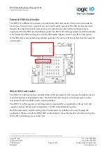
Страница 34: ... If the SIM card is removed during cellular operation the device will be rejected from the network shortly after Micro SD Card reader The RTCU NX 910 device has a standard Micro SD card reader which is located inside the device see drawing below or graphical view The Micro SD card reader is a lid based system with a mechanical lock for reliable insertion and operation The RTCU NX 910 supports a FA...

Страница 35: ...recommended to use approved Industrial Grade SD CARDs Logic IO has approved and recommends industrial grade SD CARDs from ATP that is available in capacities from 512 MB to 32 GB ATP Industrial Grade SD SDHC Cards are optimized for demanding industrial applications with consistent performance in all conditions ATP uses reliable SLC flash technology with a flash endurance more than 20 times higher ...

Страница 36: ...www logicio com Product Identification Label with Barcode The RTCU NX 910 product identification is found on the exterior of the device and contains a unique serial number in readable form and as a barcode The first three digits in the serial number identify the device type and for the RTCU NX 910 device this unique code is 332 The barcode format used 2 5 Interleaved with Check Digit ...

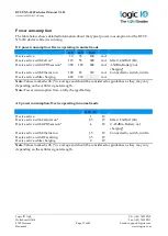
Страница 37: ...ging Device active with Ethernet on 100 45 310 mA Connected to switch in idle Device active while charging 620 310 mA Note Values marked with is average and should be considered as guidelines as they may vary depending on the cellular signal strength Note Power consumption from a fully charged battery AC power consumption Device operating in normal mode 220V AC Device active 1 W Device active with...

Страница 38: ...V 24V BAT 12V 24V BAT Cellular 20 10 50 mA RS232 1 mode 0 4 5 2 4 14 mA RS232 1 mode 1 4 2 2 13 mA RS232 2 mode 0 5 2 7 15 mA RS232 2 mode 1 4 5 2 5 14 mA RS485 1 4 5 2 5 15 mA RS485 2 4 5 2 5 15 mA RF 8 4 5 20 mA Vibration 1 1 0 7 3 5 mA Din 1 4 S0 12 10 mA Din 1 5 1 1 0 7 3 0 8 0 5 2 0 5 0 35 1 5 mA Power Failure 1 1 0 7 3 0 8 0 5 2 0 5 0 35 1 5 mA Power Apply 1 1 0 7 3 0 8 0 5 2 0 5 0 35 1 5 mA...

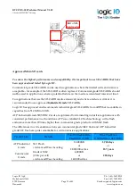
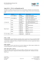
Страница 39: ...default Digital input JPDI1 Position S Position N DI1 S0 DI1 normal default JPDI2 Position S Position N DI2 S0 DI2 normal default JPDI3 Position S Position N DI3 S0 DI3 normal default JPDI4 Position S Position N DI4 S0 DI4 normal default DC Out voltage JP101 Position 12V Position 24V 12V DC out 24V DC out TER1 and TER2 Enables disables on board 120Ω line termination resistors which are according t...

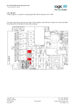
Страница 40: ...625 0211 8700 Horsens Page 40 of 45 Email support logicio com Denmark www logicio com 12V and 24V These jumpers are used for connecting the DC OUT terminal to 12V or 24V The following figure shows the location of the jumpers when the lid of the device is removed Red lined boxes show the default state of the jumpers ...

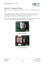
Страница 41: ...tallation of the SIM card Open the hinged lid of the SIM card reader orientate the card as shown below and insert it into the lid of the card reader Close the lid and slide the metal locking mechanism to the locked position as shown with an arrow and text on the lid until a click is heard To remove the card slide the metal locking mechanism to the unlocked position as shown with an arrow and text ...

Страница 42: ...to the reader open the hinged lid of the card reader orientate it as shown below and push the card into the lid Close the lid and slide the metal lid in the direction that is shown with an arrow on the lid until a click is heard Remove the card by sliding the lid in the direction that is shown with an arrow on the lid and then open the lid Avoid removing the Micro SD card during access to the card...

Страница 43: ...nclude several open source software tools This open source software is governed by the terms and conditions of the applicable open source license and you are bound by the terms and conditions of the applicable open source license in connection with your use and distribution of the open source software in this product Please refer to the separate document RTCU Open Source Licenses pdf for detailed ...

Страница 44: ...ed voice playback IVR Internal SIM card reader with Mini SIM 1 8 3 volt Optional eSIM RTCU M2M Platform NX32 for Linux NX32L Fully NX32 compatible Larger capacity and higher performance compared to NX32 Open and user extendable API RTCU M2M Platform SDK Audio Fully digitized audio system Transfer store and play audio Digitized cellular audio NX32L Hardware Core Cortex A5 32 bit ARM processor Hardw...

Страница 45: ... charger with temperature throttle and sub zero degrees support On board temperature sensor External Interfaces 3 x M20 cable glands SMA female connector for cellular Electrical Supply operating range 8 to 36 VDC 100 to 260 VAC Short and reverse power protected 5 V DC out 300 mA 12 24V DC out 500 250 mA Digital I O Interface 4 x relay output Max 5A 250VAC 30 VDC 5 x digital inputs Logic high 8 to ...

Отзывы: