Logic Group MATRIX ZBA Series Скачать руководство пользователя страница 22

MATRIX ZBA7140 

User’s manual


 EN 


Logic Group A/S 

Page 22 / 31 


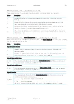
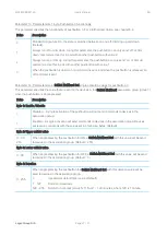
Parameter 5, Parameter size 4 bytes. LEDs colour indication. 
This parameter specifies the colour levels for the red, green and blue colours in the 4 RGB LEDs. This parameter 
is not used unless configuration parameter 4 is set to the value 2. The default configuration is a white light, where 
red level value must be higher than the two other colours in order to get a white light. 

Value 

Description 

Byte 1: Red colour level. 

0 - 255 

Specifies the level for the red colour. (Default is 255) 

Byte 2: Green colour level. 

 255 

Specifies the level for the green colour. (Default is 85) 

Byte 3: Blue colour level. 

0 - 255 

Specifies the level for the blue colour. (Default is 85) 

Byte 4: Not used. 

0  

This byte is not used and must be set to 0. 

 
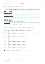
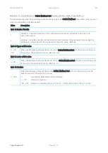
Parameter 6, Parameter size 2 bytes. Associations groups, transmission when included secure. 
This parameter specifies if commands are transmitted as a secure message for each of the association groups. 

This parameter is only used when the device is included in security mode (either S0 or S2).


Value 

Description 

All messages in all groups are sent as insecure.  

Messages in association group 2 are sent as secure. 

Messages in association group 3 are sent as secure. 

Messages in association group 4 are sent as secure. 

Messages in association group 5 are sent as secure. 

16 

Messages in association group 6 are sent as secure. 

32 

Messages in association group 7 are sent as secure. 

64 

Messages in association group 8 are sent as secure. 

128 

Messages in association group 9 are sent as secure.  

255 

All messages in all groups are sent as secure. (Default) 

 
NB. The above values are bitmasks and can be added up to select several options. 

Содержание MATRIX ZBA Series

Страница 1: ...MATRIX ZBA7140 User s manual EN Logic Group A S Page 1 31 Installation Guide and User s Manual MATRIX ZBA Type ZBA7140 Z Wave Battery Wall Controller...

Страница 2: ...MATRIX ZBA7140 User s manual EN Logic Group A S Page 2 31 Logic Group A S Vallensb kvej 22 B DK 2605 Br ndby 45 7060 2080 info logic group com www logic group com...

Страница 3: ...s 8 6 2 Controlling light dimmers 8 6 3 Sending pre configured dim levels 9 6 4 Button functions 10 6 5 Control of other devices 11 6 6 Central Scene notifications 13 6 7 LED indication 14 6 8 Battery...

Страница 4: ...t MATRIX ZBA is intended for indoor use in dry locations only Do not use in damp moist and or wet locations Do not power permanently 2 Disposal Dispose of the packaging in an environmentally friendly...

Страница 5: ...rs blinds sunscreens etc MATRIX ZBA can also issue scene activation commands that can be used to activate scenes in the Z Wave Controller MATRIX ZBA has four RGB indicator LEDs one for each pushbutton...

Страница 6: ...tStart Inclusion mode will drain the battery Figure 1 Inserting battery 5 2 Fastening MATRIX ZBA is mounted in a 1 module FUGA compatible frame The device can be mounted in the following ways A In a F...

Страница 7: ...Remove the pushbutton cover as described in the section Removing the Pushbutton Cover 2 Unscrew the screws from the wall box or wall 3 Push the device out of the frame as described in the section Remo...

Страница 8: ...ttery lifetime and the desired responses of the device The device will stay awake right after inclusion for 10 seconds allowing the controller to perform certain configuration It is possible to manual...

Страница 9: ...configuration parameters is then set to Byte 1 Enable Disable This byte must be set to 1 in order to enable the feature Byte 2 Upper switch value This byte must be set to the value 50 for sending this...

Страница 10: ...uired to use two pushbuttons to control for example a dimmer Then one pushbutton always dims up and the other pushbutton always dim down Figure 3b The last function that the pushbuttons can be configu...

Страница 11: ...illustrates a system with a MATRIX ZBA device that controls an external light dimmer with association groups In the figure the dimmer is controlled by group 5 pushbutton 2 in device 5 by sending Multi...

Страница 12: ...ons for both devices 5 and 7 by setting configuration parameters as such MATRIX ZBA device 5 o Parameter 10 2 o Parameter 16 1 MATRIX ZBA device 7 o Parameter 7 2 o Parameter 13 1 With the configurati...

Страница 13: ...eact on the different pushbutton activations Button Scene Number Key attribute 1 1 0 Key pressed one time 1 Key released 2 Key held down 3 Key pressed two times 4 Key pressed three times 2 2 0 Key pre...

Страница 14: ...ation can also be switched off When MATRIX ZBA is put into inclusion state then the first LED is flashing and this LED can also be controlled by sending Command Class Indicator messages to the module...

Страница 15: ...work it will set the device back to factory default If the device already belongs to a network follow the remove process before adding it in your network Otherwise the adding of this device will fail...

Страница 16: ...n be found on the product packaging 7 3 Z Wave Plus specific information MATRIX ZBA is a Z Wave Plus device and supports all required command classes for fulfilling the Z Wave Plus specification MATRI...

Страница 17: ...Yes COMMAND_CLASS_SECURITY Yes Yes COMMAND_CLASS_SECURITY_2 Yes Yes COMMAND_CLASS_SUPERVISION V1 Yes Yes COMMAND_CLASS_ASSOCIATION V2 Yes Yes COMMAND_CLASS_ASSOCIATION_GRP_INFO V3 Yes Yes COMMAND_CLA...

Страница 18: ...k controller is missing or is otherwise inoperable MATRIX ZBA can be factory reset by holding the switch I for at least 10 seconds the LEDs will give a short flash By following this procedure all conf...

Страница 19: ...erated It can as an example be used for controlling light dimmers Max nodes in the group 5 Pushbutton 2 Group 4 Nodes in this group receives Basic Set when pushbutton 2 is activated the on or off stat...

Страница 20: ...ff status is decided by the internal button status and is toggled between each activation Max nodes in the group 5 Group 9 Nodes in this group receives Switch Multilevel Set Switch Multilevel Start Le...

Страница 21: ...tion of double and triple activations as a new activation must be detected within this specified time for the repeatedly detection Be aware that this parameter must be lower than the value in Paramete...

Страница 22: ...ed and must be set to 0 Parameter 6 Parameter size 2 bytes Associations groups transmission when included secure This parameter specifies if commands are transmitted as a secure message for each of th...

Страница 23: ...that are sent to the devices in the Switch Multilevel association group group 3 when the pushbutton is single pressed Value Description Byte 1 Enable Disable 0 Disabled A single activation of the push...

Страница 24: ...p Devices will receive commands with the values set in 3 following bytes Default Byte 2 Upper switch value 0 99 255 When double pressing the pushbutton for ON a Switch Multilevel Set with this value w...

Страница 25: ...that are sent to the devices in the Switch Multilevel association group group 5 when the pushbutton is single pressed Value Description Byte 1 Enable Disable 0 Disabled A single activation of the pus...

Страница 26: ...p Devices will receive commands with the values set in 3 following bytes Default Byte 2 Upper switch value 0 99 255 When double pressing the pushbutton for ON a Switch Multilevel Set with this value w...

Страница 27: ...that are sent to the devices in the Switch Multilevel association group group 7 when the pushbutton is single pressed Value Description Byte 1 Enable Disable 0 Disabled A single activation of the pus...

Страница 28: ...p Devices will receive commands with the values set in 3 following bytes Default Byte 2 Upper switch value 0 99 255 When double pressing the pushbutton for ON a Switch Multilevel Set with this value w...

Страница 29: ...that are sent to the devices in the Switch Multilevel association group group 9 when the pushbutton is single pressed Value Description Byte 1 Enable Disable 0 Disabled A single activation of the pus...

Страница 30: ...p Devices will receive commands with the values set in 3 following bytes Default Byte 2 Upper switch value 0 99 255 When double pressing the pushbutton for ON a Switch Multilevel Set with this value w...

Страница 31: ...leep mode Operating temperature 10 40 C Humidity 20 95 non condensing Protection class IP20 Radio protocol Z Wave EU 868 4MHz 700 Series Approvals CE Z Wave Plus Explorer Frame Support No SDK 7 12 01...

Отзывы: