Using the IntelliLogger™
41
E
XCITATION
O
UTPUT
The ILIM-7 is equipped with a semi-regulated 5Vdc output that can be used as an excitation
source for many sensors requiring excitation (e.g. strain gauge bridge pressure sensors or
load cells). The excitation output voltage is cycled on prior to a channel reading for a period of
time then a channel reading is taken and the excitation supply is turned off.
Output Characteristics
The Excitation Output is derived from the regulated 5Vdc system voltage on the
ILIM-7. The output is controlled via a series transistor, which results in a bit of
voltage drop, resulting in an output voltage of approximately 4.8 to 4.9Vdc actual
output.
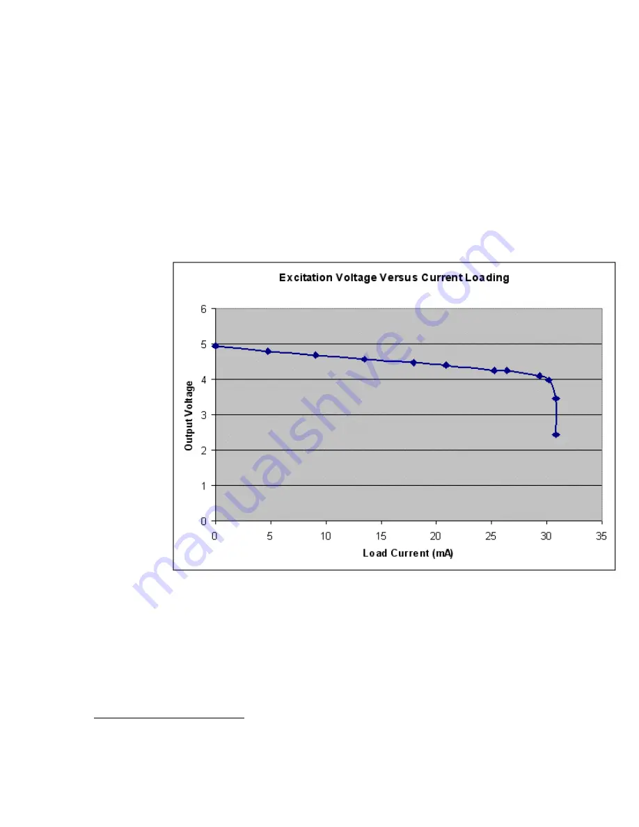
Additionally, the output incorporates over-current protection circuitry that starts
reducing the voltage when the load current draw exceeds approximately 25mA.
Figure 3-14 Excitation Output Voltage vs Current
For many sensor excitation applications, the output voltage can be measured
once with a voltage meter and this value can be used in any signal derivation
equations that are a function of the excitation voltage (e.g. bridge signals). For
applications requiring a precision known voltage supply, one of the ILIM-7
channels can be dedicated to reading the Excitation Output actual voltage and
another channel can be dedicated to reading the bridge signal output. Within the
Program Net, a Math icon can then be used to normalize the output signal as a
function of the Excitation voltage
2
.
2
For example, dividing the measured output signal (Vsignal) from a strain gauge bridge by the measured Excitation
Output voltage, Vexc will result in a normalized mV of signal per V of excitation. This normalized value can then be used
for the Engineering units calculation associated with that sensor.


