Owner’s Manual (Snowblower)
N14821 2 - September, 2002
2
Set-up and Operating Instructions Continued
Equipment Set-up Continued:
washers to secure the motor into place, but
do nottighten. Slide the drive sprocket and
1/4” x 1” key onto the output shaft of the
hydraulic motor. Adjust the sprocket and
spout gear teeth for alignment. Tighten the
bolts to secure rotator motor. Adjust the
drive sprocket so that it’s centered on the
spout gear or evenly spaced between the
sprocket guides. Tighten the set screw on
the sprocket. Attach the hydraulic hoses
(supplied by customer), check rotation of
spout, adjust if binding occurs.
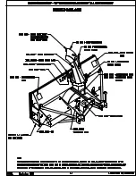
Figure 5
•
The optional electric spout control (figure 6)
is pre-assembled and will use (4) 3/8” bolts,
flat washers, lock washers and nuts to attach
the control onto the bracket as shown, do
not tighten the bolts, then align the spout
rotator gear and the drive sprocket. Tighten
the bolts, and check rotation of spout, adjust
if binding occurs.
Figure 6
Attach the wiring harness for the electric
spout control option (figure 7) as follows:
1.
Mount the 2-way selector switch in a
convenient location near the operator.
2.
Select an appropriate 12 volt power source
that will supply 10 amp’s continuously.
3.
Install a 20 amp inline fuse to the power
source.
4.
Connect a red 14 ga. wire from the outlet of
the fuse to the 2-way selector switch
terminal (figure 7). Avoid hot or moving
parts when routing wires.
5.
Locate the main ground wire from the
battery. Install a black 14 ga. wire to the
main ground (Do Not ground to the frame
of the machine, connect directly to the main
ground wire). Securely torque the hardware
retaining the main ground to the harness
ground wires.
6.
Connect the black 14 ga. wire from the main
ground to the 2-way selector switch terminal
(figure 7). Avoid hot or moving parts when
routing wires.
7.
Connect a second set of 14 ga. wires from
the 2-way selector switch to the electric
spout motor. Attach 4” jumper wires to
connect opposite terminals on the switch
(figure 7).
Figure 7
6.
Check the sprockets and drive chain for
alignment and proper tension on the chain.
Chain should have approximately one inch (1”)
of deflection.
7.
Check all bolts and set screws to insure that they
are tight.
Содержание 842S
Страница 5: ...Section 1 Safety ...
Страница 12: ......
Страница 13: ...Section 2 Operating ...
Страница 19: ...Section 3 Maintenance ...
Страница 20: ......
Страница 26: ......
Страница 27: ...Section 4 Service Parts ...
Страница 28: ......
Страница 31: ......
Страница 32: ......
Страница 33: ......
Страница 34: ......
Страница 35: ......
Страница 36: ......
Страница 37: ......
Страница 38: ......


