58
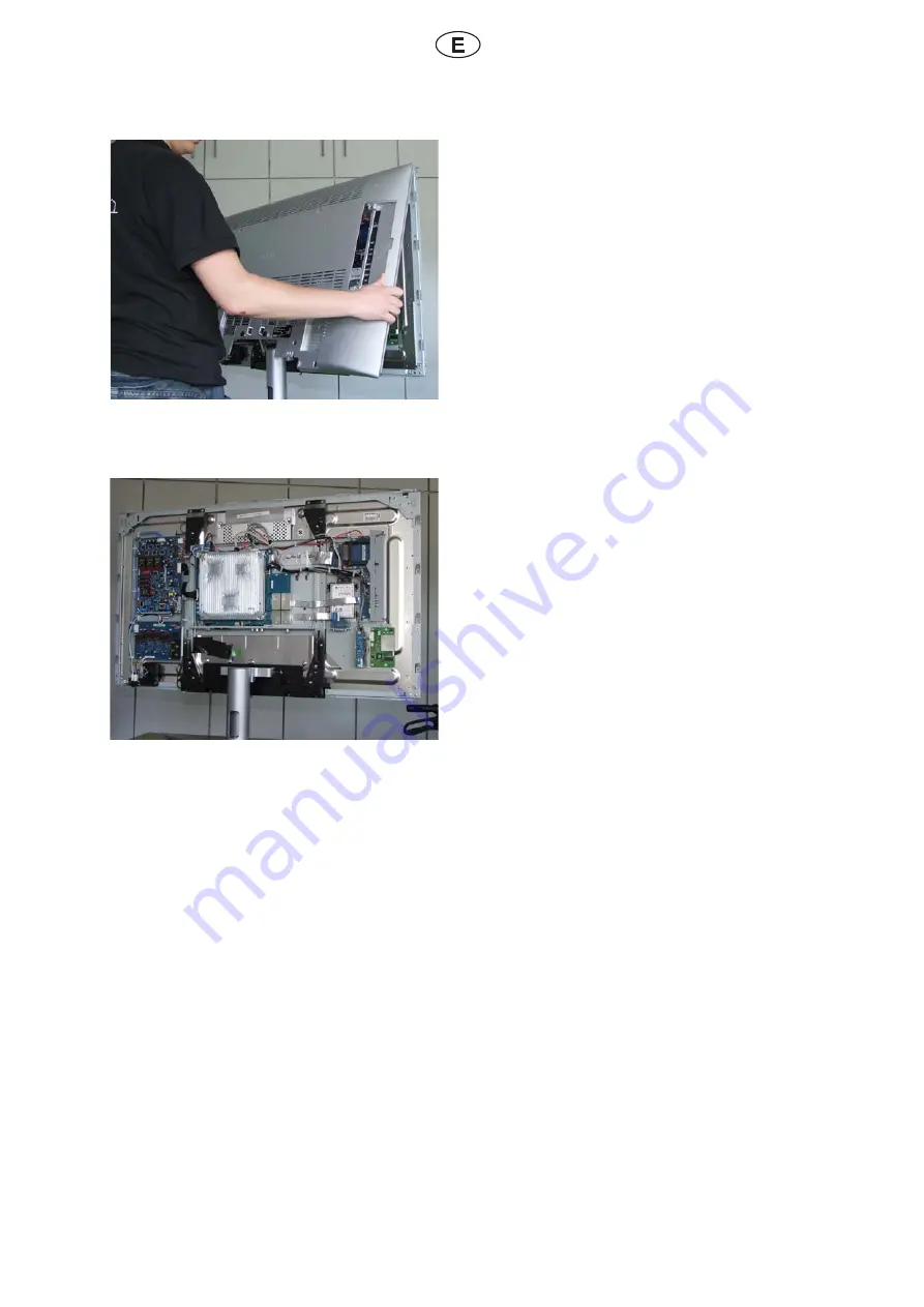
Fig. 15
+@O@QSDONRSDQHNQONCQ¨PTHS@QRDCDROT°RCDQDSHQ@QSNCNRKNRSNQMHKKNRZ\
Fig. 16
El interior del televisor queda entonces expu-
DRSNBNLNOTDCDUDQRDDMK@ÅF
Страница 1: ...e WLAN 70830 080 MRS KK SHNM HMRSQTBSHNMR ENQ QDSQN S JHSR Module WLAN 70830 080 Inbouwinstructies voor uitrustingsset Module WLAN 70830 080 Instructions de montage pour l extension Module WLAN 70830...
Страница 2: ...2 Inhalt Indice Index Inhoud Sommaire Indice Deutsch 3 Italiano 13 English 23 Nederlands 33 Francais 43 Espanol 53...
Страница 3: ...tuelle TV und DVB Software DHMYTROHDKDM CHD 2HD TMSDQ ENKFDMCDM CQDRRDM MCDM GSSO RDQUHBD KNDVD CD http infotip de Die Zahlen X in Klammern stehen f r die Positionsnummer des unter dem Gliede rungspun...
Страница 4: ...nd entfernen Sie entsprechend des TV Ger temodels die auf der entsprechenden Skizze mit Pfeilen markierten Schrauben Zum Einsetzen der R ckwand verfahren Sie entsprechend umgekehrt Vorgehensweise Abb...
Страница 5: ...netes Hilfsmittel wie Plastikkarte oder kleinen Sauger Abb 6 Abb 6 Pfeile kennzeichnet die Position der zu entfernenden Schrauben unter den Intar sien rechts und links am TV Ger t Abb 7 Ist unter Ihre...
Страница 6: ...Bedienauge kann jetzt entnommen wer den Abb 10 Vorsichtige Handhabung bei Glasscheiben Heben Sie die Ger tefront nach oben etwas an und nehmen Sie diese ab Achten Sie sp ter beim Zusammenbau darauf d...
Страница 7: ...Diese Schrauben sind zu entfernen Abb 13 Entfernen Sie die mit Pfeil markierten Schrau ben auf der R ckseite Abb 14 4MSDQ CHDRDQ K OOD AD MCDM RHBG YVDH Schrauben die entfernt werden m ssen Um den Zu...
Страница 8: ...8 Abb 15 Die R ckwand kann nach dem alle Schrauben entfernt worden sind abgenommen werden Abb 16 Der Blick in das Innere des TV Ger tes ist nun frei wie auf Abb 16 dargestellt...
Страница 9: ...m Umgang mit MOS Bauteilen Vorgehensweise Abb 17 Der mit Peil auf Abb 17 markierten Stelle zeigt den Einbauort des Modules Abb 18 Montieren Sie das Modul an entsprechendere Stelle wie dargestellt Befe...
Страница 10: ...nnen Sie mit der l ngsten Antenne oben Sichern Sie die Antennen jeweils mit einer Schraube 6 Abb 20 Stecken Sie die Stecker der Antennen am Mo dul wie dargestellt ein Abb 21 Befestigen Sie die Antenne...
Страница 11: ...11 Abb 22 Verbinden Sie Chassis und Module WLAN mit dem Kabelbaum 5 Befestigen Sie den Kabelbaum wie darge stellt Abb 26...
Страница 12: ...ront oben an das TV Ger t Schlie en das Bedienauge wieder an Befestigen Sie Bedienauge und Ger tefront mit der vorher entfernten Schraube wieder am Panelrahmen Ger tefront wieder mit den beiden Schrau...
Страница 13: ...40 46 Compose Dopo aver applicato il kit di espansione riprodurre sempre il software TV e DVB pi recente scaricabile dall indirizzo http service loewe de http infotip de I numeri tra parentesi X indi...
Страница 14: ...hi del sintonizzatore RDBNMC CDK LNCDKKN CH OO QDBBGHN 35 RUHS QD D QHLTNUDQD KD UHSH BNMSQ RRDFM SD HM FTQ BNM delle frecce Per riapplicare il pannello posteriore procedere in senso inverso Procedura...
Страница 15: ...B S oppure una piccola ventosa Fig 6 F EQDBBH HMCHB K ONRHYHNMD CDKKD UHSH da rimuoversi collocate sotto gli intarsi a destra e sinistra sull apparecchio TV Fig 7 Rimuovere l eventuale altoparlante m...
Страница 16: ...staccare il pulsante di coman do Fig 10 Eventuali lastre di vetro vanno manipolate con cura Sollevare leggermente il frontale dell apparecchio verso l alto e toglierlo Durante il montaggio successivo...
Страница 17: ...nteriore Queste viti devono essere rimosse Fig 13 Rimuovere le viti contrassegnate con freccia sul lato posteriore Fig 14 Sotto questo sportellino si trovano due viti che devono essere rimosse Sgancia...
Страница 18: ...18 Fig 15 La parete posteriore pu essere rimossa una volta tolte tutte le viti Fig 16 Ora la visuale all interno dell apparecchio TV KHADQ BNLD Q OOQDRDMS SN HM F...
Страница 19: ...tenersi alle norme d uso dei componenti MOS Procedura Fig 17 K OTMSN RDFM K SN C KK EQDBBH MDKK F indica la posizione di montaggio del modulo Fig 18 Montare il modulo nella posizione indicata nell ill...
Страница 20: ...e come illustrato Iniziare con l antenna pi lunga in alto Fissare ogni antenna con una vite 6 Fig 20 M K QD H BNMMDSSNQH CDKKD MSDMMD RTK LNCTKN come illustrato Fig 21 M K QD H BNMMDSSNQH CDKKD MSDMMD...
Страница 21: ...21 Fig 22 Fissare lo chassis e i moduli WLAN con il fascio di cavi 5 Fissare il fascio di cavi come illustrato Abb 26...
Страница 22: ...gare di nuovo il pannello frontale Fissare nella rispettiva cornice il pannello frontale e la parte anteriore dell apparecchio con la vite precedentemente rimossa Fissare nuovamente la parte anteriore...
Страница 23: ...has been installed it will be necessary to download the current TV and DVB software available under http service loewe de http infotip de The numbers in brackets X refer to the items described under...
Страница 24: ...onnections if present 4MCN MC QDLNUD SGD RBQDVR HMCHB SDC AX SGD QQNVR HM SGD QDKDU MS FTQDR MC BBNQCHMF SN SGD 35 RDS LNCDK Proceed in the reverse order to replace the rear panel Procedure Fig 2 Posi...
Страница 25: ...ion cup Fig 6 3GD QQNVR HM F HMCHB SD SGD RBQDVR TMCDQ the trim on the left and rights sides of the TV set Fig 7 If a loudspeaker is installed under your TV set it must be removed The loudspeaker prev...
Страница 26: ...F The operating eye can now be removed Fig 10 Take care when handling glass panels Remove the set front by lifting upwards and slightly outwards When later reattaching the set front be careful not to...
Страница 27: ...ndicated AX SGD QQNVR HM F These screws must be removed Fig 13 Remove the screws indicated by the arrows in F NM SGD QD Q RHCD Fig 14 Below this cover are two further screws that require removal Detac...
Страница 28: ...28 Fig 15 Once all the screws have been removed the rear panel can be detached Fig 16 The interior of the TV set is now accessible as RGNVM HM F...
Страница 29: ...atic charging Observe the rules for handling MOS components Procedure Fig 17 3GD KNB SHNM HMCHB SDC AX SGD QQNV HM F is the module s installation location Fig 18 Install the module at the indicated po...
Страница 30: ...he antennas as shown Begin at the top with the longest antenna Secure each of the antennas with a screw 6 Fig 20 Plug the antennas to the module as shown Fig 21 Secure the antennas using the self adhe...
Страница 31: ...31 Fig 22 Attach chassis and WLAN module to the ca ble harness 5 Fasten the cable harness as shown Abb 26...
Страница 32: ...the set Reattach the set front to the TV set Reattach the operating eye Fasten the operating eye and set front to the panel border with the previously removed screw Fasten the set front to the left an...
Страница 33: ...Na het installeren van de uitbreidingsset moet u altijd de actuele TV en DVB software downloaden die u kunt vinden onder de volgende adressen http service loewe de http infotip de De getallen tussen h...
Страница 34: ...ekening met pijlen aangegeven schroeven los en verwijder ze overeenkomstig het betreffende model van het tv toestel Voor het aanbrengen van de achterwand voert u dezelfde handelingen in omgekeerde vol...
Страница 35: ...een plastic kaart of een zuignapje Afb 6 Afb 6 pijl toont de positie van de te verwi jderen schroeven onder het inlegwerk rechts en links op het tv toestel Afb 7 Wanneer er onder uw tv toestel een lu...
Страница 36: ...u kan het bedieningsoog worden verwijderd Afb 10 Vorzichtig omspringen met glasplaten Til het toestelfront een beetje op en trek het vervolgens van het toestel af Let er later bij de montage op dat de...
Страница 37: ...oeven Die schroeven moeten worden verwijderd Afb 13 Verwijder de met een pijl aangeduide schroe ven in de achterwand Afb 14 Onder dit klepje bevinden zich twee schroe ven die moeten worden verwijderd...
Страница 38: ...38 Afb 15 De achterwand kan worden afgenomen nadat alle schroeven werden verwijderd Afb 16 Nu hebt u een vrije inkijk in het toestel zoals getoond in afb 16...
Страница 39: ...r het werken met MOS componenten Werkwijze Afb 17 De met de pijl aangeduide plaats in afb 17 is de inbouwplaats van de module Afb 18 Monteer de module op de daartoe bestemde plaats zoals getoond Beves...
Страница 40: ...s afgebeeld Begin met de langste antenne bovenaan DUDRSHF CD MSDMMDR SDKJDMR LDS M RBGQNDE 6 Afb 20 Steek de stekkers van de antennes zoals ge toond in de module Afb 21 Bevestig de antennes met behulp...
Страница 41: ...41 Afb 22 Verbind het chassis en de WLAN module met de kabelbundel 5 Bevestig de kabelbundel zoals getoond Abb 26...
Страница 42: ...ont opnieuw boven aan het tv toestel Sluit het bedieningsoog opnieuw aan Bevestig het bedieningsoog en het toestelfront met de eerder verwijderde schroeven weer aan het panelframe Zet het toestelfront...
Страница 43: ...nsion veuillez toujours installer les logiciels TV et DVB actuels que vous trouverez aux adresses suivantes http service loewe de http in fotip de DR BGHEEQDR 7 DMSQD O QDMSG RDR C RHFMDMS KD MTL QN C...
Страница 44: ...UDY RDKNM KD LNC KD CD S K UHRDTQ KDR UHR L QPT DR O Q CDR BGDR RTQ KiHKKTRSQ SHNM correspondante NTQ QDLDSSQD DM OK BD K O QNH QQH QD OQNB CDY CD K L LD E NM KiHMUDQRD QNB CTQD Ill 2 K BDY RH ONRRHAK...
Страница 45: ...D NT une petite ventouse Ill 6 2TQ KiHKK K BGD HMCHPTD K ONRHSHNM CDR UHR QDSHQDQ RNTR Ki K LDMS CiG AHKK FD CQNHSD DS F TBGD CT S K UHRDTQ Ill 7 2H TM G TS O QKDTQ DRS LNMS DM CDRRNTR CD UNSQD S K UH...
Страница 46: ...C RNQL HR SQD QDSHQ Ill 10 5HSQDR DM UDQQD L MHOTKDQ UDB OQ B TSHNM Soulevez quelque peu l avant de l appareil vers le haut et enlevez le En remontant l appareil par la suite veil lez ne pas coincer...
Страница 47: ...O Q KDR BGDR DR UHR CNHUDMS SQD QDSHQ DR Ill 13 1DSHQDY KDR UHR HMCHPT DR O Q KDR BGDR RTQ K face arri re Abb 14 M CDRRNTR CD BD UNKDS CDTW UHR CNHUDMS SQD QDSHQ DR S BGDY BD UNKDS ONTQ ONTUNHQ BB CDQ...
Страница 48: ...48 Ill 15 O QNH QQH QD ODTS SQD DMKDU TMD ENHR PTD SNTSDR KDR UHR NMS S QDSHQ DR Ill 16 iHMS QHDTQ CT S K UHRDTQ DRS C RNQL HR UHRHAKD BNLLD QDOQ RDMS RTQ KiHKK...
Страница 49: ...e manipulation des composants MOS QNB CTQD Ill 17 iDLOK BDLDMS HMCHPT O Q K BGD RTQ KiHKK QDOQ RDMSD KiDLOK BDLDMS ONTQ KD LNMS ge du module Ill 18 NMSDY KD LNCTKD KhDMCQNHS OOQNOQH BNL LD HMCHPT HWDY...
Страница 50: ...cez par l antenne la plus longue en haut Fixez les antennes avec une vis 6 pour cha cune d entre elles Ill 20 M BGDY K BGD CDR MSDMMDR C MR KD LNCT KD BNLLD QDOQ RDMS Ill 21 Fixez les antennes l aide...
Страница 51: ...51 Ill 22 Reliez le ch ssis et le module WLAN avec le faisceau de c bles 5 HWDY KD E HRBD T CD B AKDR BNLLD QDOQ RDM S Abb 26...
Страница 52: ...ordez l anneau de commande Fixez l anneau de commande et l avant de l appareil nouveau sur le bord du panel en TSHKHR MS KDR UHR DMKDU DR OQ B CDLLDMS HWDY MNTUD T Ki U MS CD Ki OO QDHK Ki HCD CDR CDT...
Страница 53: ...LOKH BH M CDAD HMRS K Q RHDLOQD DK RNESV QD BST K O Q DK televisor y el DVB que encontrar en las siguientes p ginas web http service loewe de http infotip de NR M LDQNR j 7 k PTD O QDBDM DMSQD O Q MSD...
Страница 54: ...X QDSHQD RDF M DK LNCDKN CD SDKDUHRNQ KNR SNQMHKKNR RD K CNR BNM DBG R DM DK DRPTDL correspondiente Para colocar la pared posterior proceda a la inversa Procedimiento Fig 2 Coloque el televisor de mo...
Страница 55: ...mo una tar jeta pl stica o una peque a ventosa Fig 6 R DBG R CD K F RD K M K ONRHBH M CD los tornillos que deben retirarse debajo de las piezas laterales a la derecha e izquierda del televisor Fig 7 S...
Страница 56: ...tirarse el anillo de mando Fig 10 Trate las placas de cristal con cuidado Levante ligeramente la parte frontal del tele visor y ret rela Aseg rese durante el montaje posterior de que el cable del anil...
Страница 57: ...QSD EQNMS K Estos tornillos deben retirarse Fig 13 Retire los tornillos se alados con la fecha de la parte posterior Fig 14 Debajo de esta tapa se encuentran dos tornil los que deben retirarse Para ac...
Страница 58: ...58 Fig 15 O QSD ONRSDQHNQ ONCQ PTHS QRD CDROT R CD QDSHQ Q SNCNR KNR SNQMHKKNR Z Fig 16 El interior del televisor queda entonces expu DRSN BNLN OTDCD UDQRD DM K F...
Страница 59: ...troest ticas Siga las normas para el manejo de componentes MOS Procedimiento Fig 17 DBG DM K F RD K DK KTF Q CD LNM taje del m dulo Fig 18 Monte el m dulo en el lugar correspondiente como se muestra I...
Страница 60: ...muestra Comience por la antena m s larga arriba Fije las antenas con el tornillo correspon diente 6 Fig 20 Enchufe el conector de la antena al m dulo como se muestra Fig 21 Fije la antena con ayuda d...
Страница 61: ...61 Fig 22 Conecte el chasis y el m dulo WLAN con el QM R CD B AKDR Fije el mazo de cables como se muestra Abb 26...
Страница 62: ...ior del televisor Vuelva a conectar el anillo de mando Fije de nuevo el anillo de mando y la parte frontal del televisor con el tornillo retirado previamente en el marco del panel 5TDKU I Q K O QSD EQ...
Страница 63: ...63...
Страница 64: ...on 09261 99 0 Telefax 09261 95411 Hotline Telefon 0180 5221801 e mail loewe loewe de http www loewe de 05 2010 Printed in Germany KB 05 10 nderungen vorbehalten NM QHRDQU CH LNCH BGD 2TAIDBS SN LNCH B...