Lochinvar 1,260,000 Скачать руководство пользователя страница 7

Installation and

Service Manual

7

Base for Combustible Floors

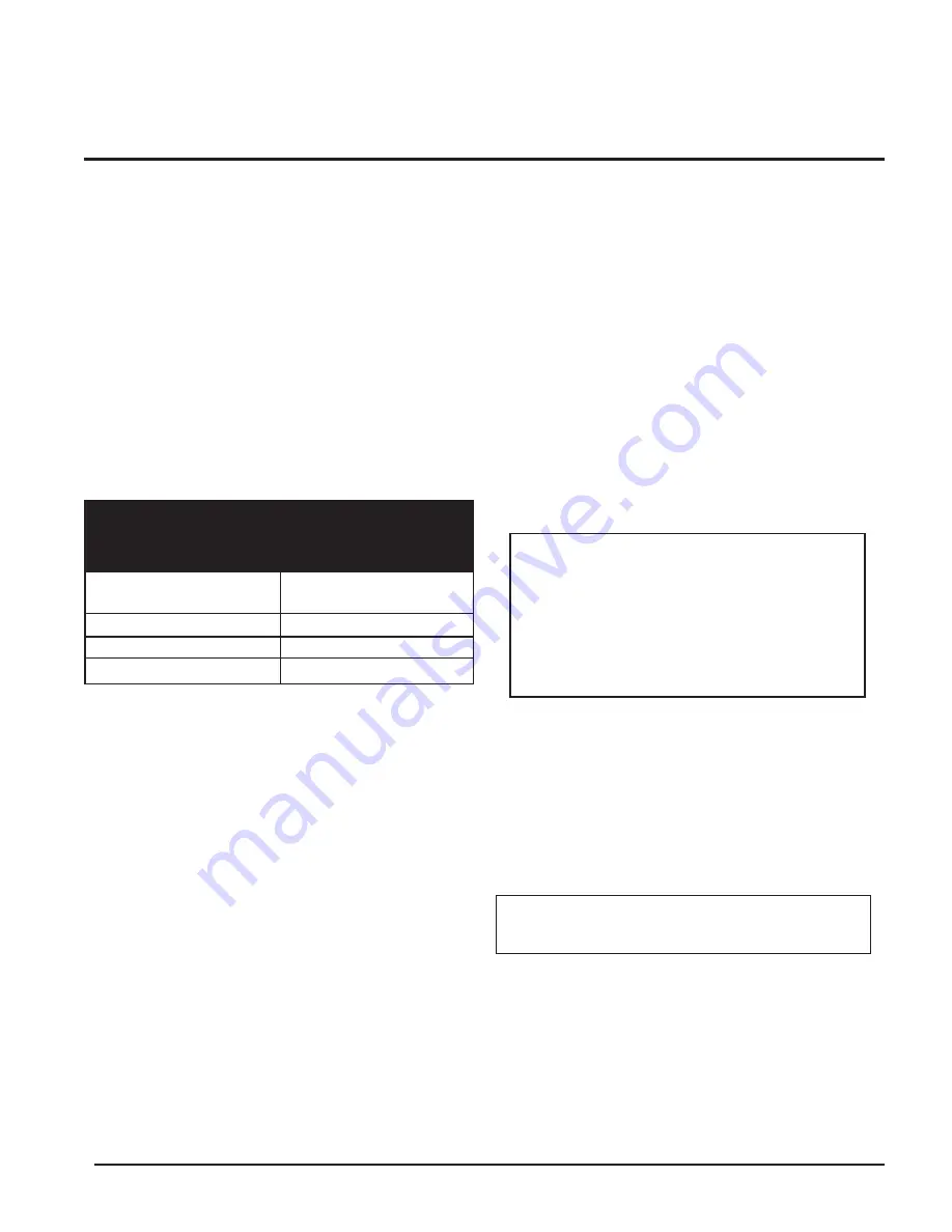
There are no manufactured combustible floor base kits
available for 

990,000 - 2,070,000

Btu models.  See Table-A

below for floor base kits that are available.  

You must construct a base for combustible floor installation.
Install unit over a base of hollow clay tiles or concrete blocks
from 8" to 12" thick and extending at least 24" beyond the unit
sides. Place tiles or blocks so that the holes line up horizontally
to provide a clear passage through the tiles or blocks. Place a
1/2" fireproof millboard over the top of the tile or block base.
Place a 20-gauge sheet metal cover over the fireproof
millboard. Center the unit on the base. Also follow this
procedure if electrical conduit runs through the floor beneath
the unit. This base must meet all local fire and safety codes.

FREEZE PROTECTION

Although these units are CSA International design certified for
outdoor installations, such installations are not recommended
in areas where the danger of freezing exists. You must provide
proper freeze protection for outdoor installations, units
installed in unheated mechanical rooms or where temperatures
may drop to the freezing point or lower. If freeze protection is
not provided for the system, a low ambient temperature alarm
is recommended for the mechanical room. Damage to the unit
by freezing is non-warrantable.

Anytime the temperature measured at any of the sensors
(except the outside air temperature sensor) drops below 35°F
(2°C),  the control turns on the pump contact and the alarm
relay. The screen displays an error message (EO2).

Pump Operation

This unit is equipped with a pump delay feature as standard.
The delay is selectable through the temperature controller. As
shipped from the factory, the 

Δ

T

MIN

is set to “OFF”, which

creates a 30 second pump delay at the end of a Call for Heat.

The value of 

Δ

T

MIN

can be  changed to a value between 1°F

and 20°F. This will cause the unit to continue pump operation
until the 

Δ

T is less than the value selected (30 second

minimum).

A value of “ON” is selectable through the control for 

Δ

T

MIN

.

This will operate the pump continuously. Alternatively, the
pump can be powered by a separate circuit for continuous
operation.

Note:

Pump relay is rated for 1 HP maximum.

Location

Locate indoor boilers and hot water supply boilers in a room
having a temperature safely above freezing [32°F (0°C)]. 

Hydronic System Antifreeze

Freeze protection for a heating boiler or hot water supply
boiler using an indirect coil can be provided by using hydronic
system antifreeze. Follow the appliance manufacturers
instructions. Do not use undiluted or automotive type
antifreeze.

Outdoor Boiler Installation

Adequate hydronic system antifreeze must be used. A snow
screen should be installed to prevent snow and ice
accumulation around the unit or its venting system. 

WARNING

: Do not use antifreeze in

domestic water heater applications.

CAUTION

: A mechanical room

operating under a negative pressure may
experience a down draft in the flue of a
boiler which is not firing. The cold outside
air pulled down the flue may freeze a heat
exchanger. This condition must be
corrected to provide adequate freeze
protection. 

399,999

CFK3301

500,000

CFK3302

650,000

CFK3303

750,000

CFK3304

TABLE - A

COMBUSTIBLE FLOOR KITS

Input Btu/hr

Kit Number

Содержание 1,260,000

Страница 1: ...rtment Installation and service must be performed by a qualified installer service agency or the gas supplier WARNING Do not use this appliance if any part has been under water The possible damage to...

Страница 2: ...ions 32 Relief Valve 33 Water Flow Switch 33 Low Water Cutoff 33 Connecting to Electrical Supply 33 Boiler System Piping 34 Primary Secondary Boiler Piping 35 Table of Contents Low Temperature Return...

Страница 3: ...th skin and eyes Use NIOSH certified dust respirator N95 http www cdc gov niosh hompage html Lightly mist with water only those areas being handled the combustion chamber lining or base insulation to...

Страница 4: ...ls away from operation of the hot unit Severe burns can occur 7 You must take adequate care to prevent scald injury when storing water at elevated temperatures for domestic use 8 This unit must have a...

Страница 5: ...Installation and Service Manual 5 PRODUCT IDENTIFICATION FIG 1 Front and Rear View Rear View Front View...

Страница 6: ...le floor 7 Do not install unit directly on carpet or other combustible material A concrete over wood floor is not considered non combustible Maintain required clearances from combustible surfaces If i...

Страница 7: ...lay The screen displays an error message EO2 Pump Operation This unit is equipped with a pump delay feature as standard The delay is selectable through the temperature controller As shipped from the f...

Страница 8: ...to the system COMBUSTION AND VENTILATION AIR Provisions for combustion and ventilation air must be in accordance with Section 5 3 Air for Combustion and Ventilation of the latest edition of the Nation...

Страница 9: ...of the top of the enclosure FIG 6 Outside Combustion Air Single Opening Two Openings The combustion air opening must have a minimum free area of one square inch per 4000 Btu hr input 5 5cm2 per kW Yo...

Страница 10: ...than 100 square inches 645cm2 FIG 9 Combustion Air from Interior Space All dimensions are based on net free area in square inches Metal louvers or screens reduce the free area of a combustion air open...

Страница 11: ...t sagging Provide an upward slope of at least 1 4 inch per foot 21mm m on all horizontal runs from the unit to the vertical flue run or to the vent terminal on sidewall venting installations Do not us...

Страница 12: ...ators and relief equipment Never locate vent cap above or below electric meters gas meters regulators and relief equipment unless a 4 foot 1 2m horizontal clearance is maintained Terminate the venting...

Страница 13: ...prevent moisture in the cool incoming air from condensing and leaking from the inlet pipe Length of Air Inlet Pipe The installed length of air inlet pipe from the unit to the outside air inlet cap mu...

Страница 14: ...bustion Air Inlet Clearances You must locate the air inlet termination elbow at least 12 30cm above the roof or above normal snow levels 12 3 TABLE C Minimum Recommended Combustion Air Supply To Boile...

Страница 15: ...or rooftop See page 17 for venting details 3 Sidewall Venting This option uses a powered vent assembly to exhaust the flue products out a sidewall vent termination Combustion air is supplied from the...

Страница 16: ...as direct as possible with no reduction in diameter Use the National Fuel Gas Code venting tables for double wall vent to properly size all vent connectors and stacks Follow the vent manufacturer s i...

Страница 17: ...ney to generate proper draft This will result in condensing of flue products damage to the masonry flue tile insufficient draft and possible spillage of flue products into an occupied living space Car...

Страница 18: ...let see FIG 20 you must order the rooftop air inlet kit from the appliance manufacturer The part number for each VDK kit is listed by unit size in TABLE D Purchase the flue pipe rooftop flue terminati...

Страница 19: ...ors and stacks Follow the vent manufacturer s instructions when installing Type B vents and accessories such as firestop spacers vent connectors thimbles caps etc When planning the venting system avoi...

Страница 20: ...he vent Secure the trap loop in position with nylon wire ties Use caution not to collapse or restrict the condensate drain line with the nylon wire ties The condensate drain must be routed to a suitab...

Страница 21: ...lls combustion air from the outdoors through a sidewall air inlet Follow all requirements in Sidewall Venting page 19 The Horizontal DirectAire vent system requires you to install two vent pipes direc...

Страница 22: ...er assembly vent termination DV box adapter sidewall air inlet cap and a barometric damper 5 Direct Venting This option uses sealed AL29 4C vent materials for the flue outlet piping and separate combu...

Страница 23: ...he flue must be reassembled and resealed according to the vent manufacturer s instructions The installed length of flue from the unit to the outside point of termination must not exceed 50 equivalent...

Страница 24: ...Inc Corr Guard Vent 1 800 835 2830 Combustion Air Inlet Piping The Direct Vent system requires the installation of a pipe to supply combustion air from the outdoors directly to the unit Make sure the...

Страница 25: ...Corning or General Electric 2 On horizontal runs do not install vent pipe with seams pointing down Position vent pipe so that the seams are on the top side of the vent pipe 3 Secure all joints with a...

Страница 26: ...ou must locate the horizontal air inlet termination point at least 12 30cm above grade and above normal snow levels If the air inlet cap is within a 10 foot 3 05m radius of the flue outlet the point o...

Страница 27: ...around outdoor installations can change with time Do not allow the growth of trees shrubs or other plants to obstruct the proper operation of the outdoor vent system Do not install in locations where...

Страница 28: ...eration Gas Piping To safely operate this unit you must properly size the gas supply piping See TABLES J K L for piping and fitting requirements Gas pipe size may be larger than heater connection For...

Страница 29: ...om the gas line may require multiple reset functions of the ignition control module to achieve proper ignition Gas Train and Controls Note The gas train and controls assembly provided on this unit hav...

Страница 30: ...witch to the OFF position 2 Turn gas valve knobs to the OFF position 3 Shut off gas supply at the field installed manual gas cock in the gas piping to the unit If fuel supply is L P gas shut off gas s...

Страница 31: ...513 472 441 2 4 100 2 820 2 260 1 950 1 720 1 560 1 440 1 330 1 250 1 180 1 100 974 871 820 2 1 2 6 460 4 460 3 610 3 100 2 720 2 460 2 310 2 100 2 000 1 900 1 700 1 540 1 400 1 300 3 11 200 7 900 6...

Страница 32: ...unit may shut down and recycle when the regulator cover screw is removed This is normal 13 Turn the regulator adjustment screw clockwise to raise the regulator gas pressure Turn the regulator adjustme...

Страница 33: ...re a minimum flow of 26 GPM to make the flow switch and start burner operation Ensure that the pump installed on the unit will supply adequate flow to make the flow switch contacts and operate the uni...

Страница 34: ...ief valve to a suitable floor drain See the relief valve section in this manual General Plumbing Rules 1 Check all local codes 2 For serviceability of boilers always install unions 3 Always pipe the p...

Страница 35: ...anufacturers instructions included in the instruction package Primary Secondary Boiler Piping Boiler installations with a primary secondary piping system as shown in FIG 36 are recommended This type o...

Страница 36: ...cause operational problems bad combustion sooting flue gas spillage and reduced service life of the vent system and related components The bypass allows part of the boiler discharge water to be mixed...

Страница 37: ...e to excessive oxygenation is non warrantable T T T T 10 F 20 F 30 F 40 F Input Output GPM FT HD GPM FT HD GPM FT HD GPM FT HD 399 999 339 999 68 7 4 34 2 4 23 1 1 17 0 6 500 000 425 000 42 4 1 28 1 6...

Страница 38: ...cing the Boiler in Operation Filling the System All air must be purged from the system for proper operation An air scoop and air vent must be located close to the boiler outlet and there should be a m...

Страница 39: ...uctstat to delay circulator operation Also omit thermostat flow checks as the boiler is cold when heating thermostat is satisfied This provides greater economy over maintaining standby heat see FIG 41...

Страница 40: ...iority Override or an Outdoor Air Lockout Override This operation is not possible with Modes 2 or 3 The value of BOIL DSGN should be adjusted to a temperature setting that will satisfy the DHW require...

Страница 41: ...TINUOUS 1C 1NO 2C 2NO 3C 3NO 4C 4NO A1 A2 A3 B1 B2 B3 INTERMITTENT STAGE 4 STAGE 1 HeatDem1 STAGE 2 STAGE 3 HeatDem2 COM OK FAIL COM OK FAIL Figure 42F FIELD INSTALLED SAFETY DEVICES CONTINUOUS 1C 1NO...

Страница 42: ...ocated to the left of pull out control circuitry tray see FIG 44 6 Turn power switch to OFF position 7 This unit is equipped with ignition devices which automatically light the burners Do not try to l...

Страница 43: ...8 F 5 C 4 110 F 43 C 8 F 5 C Re program the set points and differentials to meet your system requirements The temperature control uses a Liquid Crystal Display LCD for interactive prompting during pr...

Страница 44: ...ither F or C OUTDR START Outdoor starting temperature Mode 1 Mode 1 no outdoor sensor outdoor sensor Mode 2 Mode 3 STG MODE Models 650 990 STG MODE Models 650 990 STG MODE Models 650 990 STG MODE Mode...

Страница 45: ...1 2 3 and 4 or 3 4 1 and 2 This allows greater programming flexibility to meet your individual needs Note One ignition system controls 1 3 stages on the 399 999 750 000 Btu hr models Operating Modes...

Страница 46: ...Sensor This sensor measures the inlet water temperature coming into the unit This is the default controlling sensor as shipped from the factory Outlet Water Temperature Sensor This sensor measures th...

Страница 47: ...ation using the outside air temperature sensor The PID method of staging allows the control to decide the most effective way to operate the stages to maintain an accurate temperature and minimize shor...

Страница 48: ...g See TABLE Q page 44 for Mode 2 Adjust Menu settings Programming For Mode 3 Sequenced Operation Mode 3 is for sequenced operation A Building Management System will sequence the operation of the unit...

Страница 49: ...rd lockout condition requiring pushing of the reset button to recycle the control or a soft lockout condition which may recycle after an approximate five minute waiting period This soft lockout condit...

Страница 50: ...ching relays for component operation and wiring harness connections to the unit s components The control panels are common and may be switched between units for troubleshooting Removing the Control Pa...

Страница 51: ...e stages to allow time for the system temperature to settle before additional stages are applied to the load This will help prevent short cycling OPERATION AND DIAGNOSTIC LIGHTS The control panel has...

Страница 52: ...r on 990 000 2 070 000 Btu hr models 5 Common manifold piping for multiple unit installations will require larger minimum pipe sizes and tank circulating tappings to ensure proper flow See TABLE X pag...

Страница 53: ...must be connected to a properly sized pump that circulates water between the heater and storage tank 2 Pump is sized to heater input and water hardness Care should be taken to size pump correctly See...

Страница 54: ...tronic control is factory pre set at approximately 125 F 52 C or less Households with small children or invalids may require 120 F 49 C or lower temperature hot water to reduce risk of scald injury Op...

Страница 55: ...Units may be supplied with an optional pressure only relief valve s When a water heater equipped with this optional relief valve is piped to a separate storage vessel the storage vessel must have a p...

Страница 56: ...ly be performed by a qualified serviceman or installer Proper service is required to maintain safe operation Properly installed and adjusted units seldom need flue cleaning Burner Removal and Cleaning...

Страница 57: ...d on the secondary side of the transformer A tripped circuit breaker indicates a short in the 24VAC controls that must be corrected Combustion and Ventilation Air Combustion Air Filter This unit has a...

Страница 58: ...Air flash code If necessary soft lockout can be circumvented by cycling power to the ON OFF switch to cycle power to the unit Note If the unit has been firing recently allow the unit to cool for five...

Страница 59: ...going into an idle state after completion of a successful call for heat Note The following descriptions do not include remotely connected devices that may be connected to the unit Refer to the wiring...

Страница 60: ...sure switch when it senses heat mode is desired IGNITION MODULE Controlled by Electronic Temperature Controller Upon sensing the 24VAC delivered to the ignition module by the electronic controller the...

Страница 61: ...Heat Exchanger Once flame has been proven the ignition module will hold the gas valves open as long as there is proof of flame and a call for heat is present Depending upon the number of stages being...

Страница 62: ...relay secure NO YES Check air pressure switch for correct pressures Replace air pressure switch Correct air settings May have to clean burners heat exchanger YES Trial for ignition completes and gas...

Страница 63: ...s YES Replace air pressure switch NO Correct air settings may have to clean burners heat exchanger YES Does igniter s proof NO Check Amp draw for 3 1 amps or greater NO Is Air Switch bouncing YES Repl...

Страница 64: ...TOR MAIN UNIT CONNECTOR IGNITER CONNECTOR 14 15 16 17 18 19 20 21 22 23 13 24 n a n a TH 4 1 5 6 9 7 BL BL BK Y BL BK W Y GY TUBING SHRINK CONNECTED UNLESS ALARM ADDED LBL20009 REV A CONNECTION WIRING...

Страница 65: ...ITTENTLY MONITORED FIELD INSTALLED SAFETY DEVICES NOTE SHOWN WITH SHORTING BARS REMOVED AND ATTACHED DEVICES IN NON ALARM STATE CONTINUOUS INTERMITTENT COM COM FAIL OK OK FAIL HIGH LOW GAS AUX HI LIMI...

Страница 66: ...Hydronic Heating Boilers and Domestic Water Heaters 66 WIRING BOX CONNECTIONS WIRING DIAGRAM B 399 999 750 000 BTU HR MODELS...

Страница 67: ...Installation and Service Manual 67 WIRING BOX CONNECTIONS WIRING DIAGRAM B CONTINUED 399 999 750 000 BTU HR MODELS...

Страница 68: ...AY W WHITE BK BLACK PR PURPLE BL BLUE P PINK O ORANGE 4 WHEN REPLACING DAMAGED WIRING USE EQUIVALENT TYPE AND GAUGE TD P P PROBE BL BK Y PUMP STAGE 2 STAGE 4 STAGE 3 AE PU LE PR HIGH LOW BL W OPTIONAL...

Страница 69: ...W P Y BL R O T W G PR BK GY W W BK GY W GY W G G GY W GY GY W O P Y BL R T G PR BK GY W BK GY GY GY BL W BR W PR BR W T PR BK BK BK W BK W BK BK W BK W R O R O O W Y R BK BK BK R R W W T T W BK G W BK...

Страница 70: ...Hydronic Heating Boilers and Domestic Water Heaters 70 WIRING BOX CONNECTIONS WIRING DIAGRAM B CONNECTIONS 990 000 2 070 000 BTU HR MODELS...

Страница 71: ...Installation and Service Manual 71 DIAGRAM B CONNECTIONS 990 000 2 070 000 BTU HR MODELS CONTINUED...

Страница 72: ...nd the LBLs on pages 64 65 68 69 Revision 7 ECO C02822 reflects moving FIG 22A page 20 to page 23 and adding Aire Lock to the title Revision 8 ECO C02870 reflects the addition of a mixing valve to FIG...

Отзывы: