background image

MADE IN USA

Serial

Nr

:

Phone#

513.528.5674

http://www

.LNSAmerica.com

Main

fax#

513.528.5733

Service

fax#

513.528.8320

LNS

America,

Inc.

USA

4621

East

Tech

Drive

Cincinnati,

Ohio

45245

CNC

CNC

CNC

QUICK

SIX

QUICK

SIX

QUICK

SIX

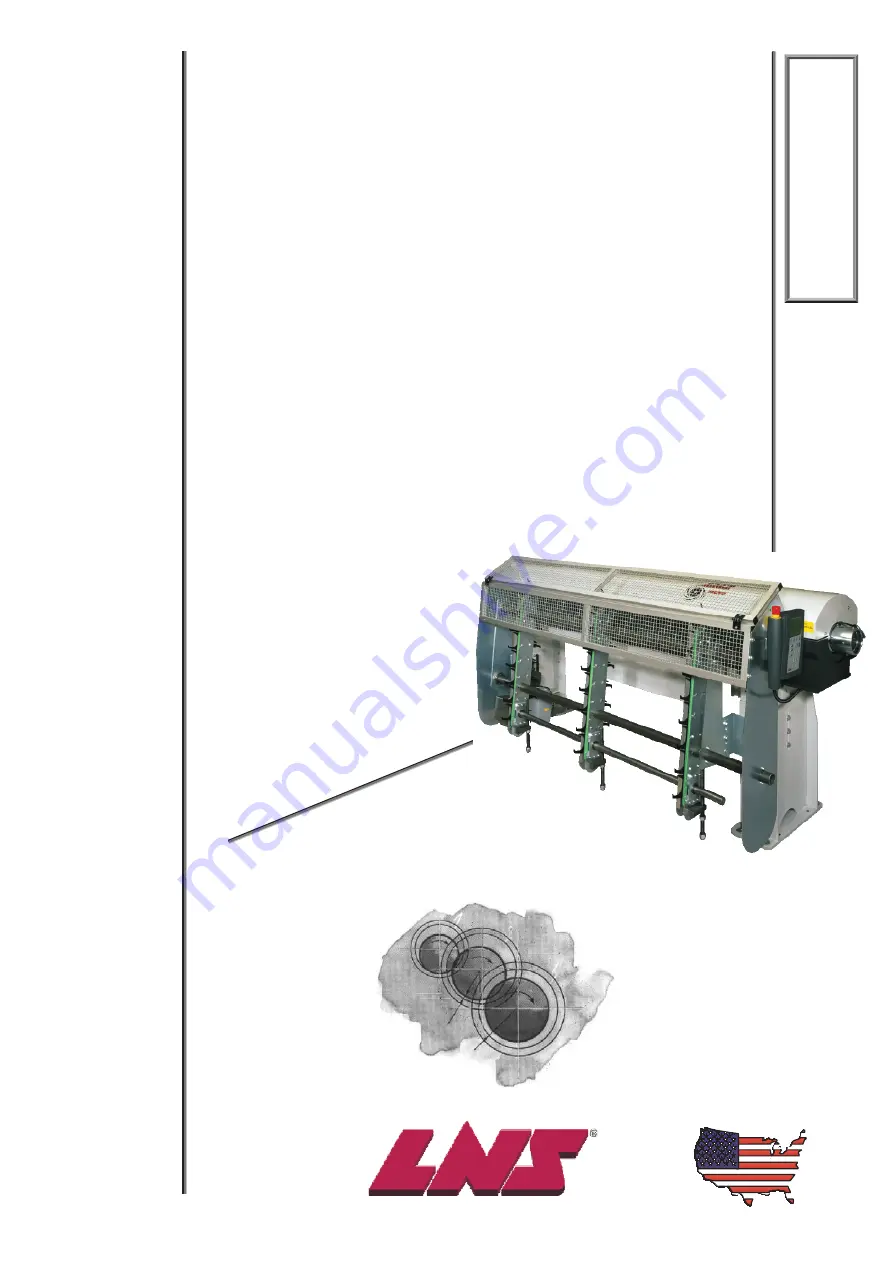
TROUBLESHOOTING

AND

SPARE

PARTS

MANUAL

TROUBLESHOOTING

AND

SPARE

PARTS

MANUAL

TROUBLESHOOTING

AND

SPARE

PARTS

MANUAL

Содержание QUICK SIX

Страница 1: ...in fax 513 528 5733 Service fax 513 528 8320 LNS America Inc USA 4621 East Tech Drive Cincinnati Ohio 45245 CNC CNC CNC QUICK SIX QUICK SIX QUICK SIX TROUBLESHOOTING AND SPARE PARTS MANUAL TROUBLESHOO...

Страница 2: ...ted 1 25 Pusher Support Down Motion Not Completed 1 26 Guiding Channel First Section Not Fully Open 1 27 Guiding Channel First Section Not Fully Closed 1 28 Guiding Channel Second Section Not Fully Op...

Страница 3: ...Maintenance 5 2 Weekly Maintenance 5 2 Monthly Maintenance 5 2 Annual Maintenance 5 3 Chapter 6 6 1 Spare Parts 6 1 Recommended Spare Parts List 6 2 Parts Order Form 6 3 Electrical Box Components 6 4...

Страница 4: ...d on the remote control station Also provided are some possible causes as to why the error has occurred This troubleshooting guide discusses every alarm that the bar feed may generate In conjunction w...

Страница 5: ...1 2 Chapter 1 Alarms QUICK SIX SQ12 SQ11 M5 SQ14 SQ12 SQ2...

Страница 6: ...ximity switch SQ3 Opening guiding channel control switch SQ4 Closing guiding channel control switch SQ5 Bearing blocks 1 open SQ6 Bearing blocks 2 closed SQ7 Control switch pusher in rear park positio...

Страница 7: ...e the bar feed sends an alarm to the machine the machine will in return send an emergency stop alarm to the bar feed which overrides any bar feed alarms Once the bar feed alarm is overridden the only...

Страница 8: ...Press the HELP key on the remote control station Press the F4 key Page Down icon twice Case Input Remote Pendant Solution 1 Bit 0 0 MODULE 0 76543210 0 Verify that the 1 0 connector is plugged into th...

Страница 9: ...sh button is pressed in Solution Press the HELP key on the remote control station Press the F4 Page Down icon twice Case Input Remote Pendant Solution 1 Bit 3 1 MODULE 0 76543210 1000 Alarm needs to b...

Страница 10: ...ation is pressed in Solution Press the HELP key on the remote control station Press the F4 Page Down icon twice Case Input Remote Pendant Solution 1 Bit 2 1 MODULE 0 76543210 100 Alarm needs to be cle...

Страница 11: ...r feed does not alarm out until the chuck is open Solution Press the HELP key on the remote control station Press the F4 key Page Down icon twice Case Input Remote Pendant Solution 1 Bit 6 1 MODULE 0...

Страница 12: ...the air pressure switch Solution Press the HELP key on the remote control station Press the F4 Page Down icon twice Case Input Remote Pendant Solution 1 Bit 5 1 MODULE 0 76543210 100000 Alarm needs t...

Страница 13: ...the operator or service technician needs to perform any work inside the unit Solution Press the HELP key on the remote control station Press the F4 key Page Down icon twice Case Input Remote Pendant S...

Страница 14: ...acted for spindle liner changeover Solution Press the HELP key on the remote control station Press the F4 key Page Down icon twice Case Input Remote Pendant Solution 1 Bit 1 1 MODULE 0 76543210 10 Put...

Страница 15: ...ion 1 Bit 2 1 MODULE 2 76543210 1 Alarm needs to be cleared Press the STOP key on the remote control station to clear the message and reset the alarm Check to see if there is any obstruction interferi...

Страница 16: ...ER TO INSTRUCTION MANUAL A023 Description The Servo Drive Alarm occurs if the Mitsubishi servo amplifier generates an alarm Solution Turn the main power off to the Quick Six for 2 seconds and turn the...

Страница 17: ...n a servo lock condition If the servo amplifier does not recognize the signal after 3 seconds this alarm is generated Solution Verify that the CN1B connector is seated properly in the allotted socket...

Страница 18: ...es a certain limit the PLC instructs the servo amplifier to quit pushing and this alarm message appears on the remote control station Solution Seq Solution Alarm needs to be cleared Press the STOP key...

Страница 19: ...ce Case Input Remote Pendant Solution 1 Bit 5 1 MODULE 1 76543210 100000 Alarm needs to be cleared Press the STOP key on the remote control station to clear the message and reset the alarm Check to se...

Страница 20: ...r profiled material the bar stock is brought to the back of the clamping device When this position is reached the spindle is jogged at a very low rpm and the pusher begins a pecking motion until the p...

Страница 21: ...when the PLC sends a message to the servo amplifier and the message is not confirmed by the servo amplifier via a checksum or vice versa This is generated if one of three conditions is not met 1 The...

Страница 22: ...uence when the output for the indexing motor M5 is active and the state of the input I1 0 SQ2 bar magazine diameter adjustment proximity switch does not change Solution Alarm needs to be cleared Press...

Страница 23: ...Closed Prior To Completing The Feed Out alarm occurs if the input for the clamping device closed is detected before the value of the Input Part Length parameter is reached Solution Verify that the cla...

Страница 24: ...f the value set in OVERALL PART LENGTH is not reached within 1 minute after the bar feed is commanded to feed out Solution Alarm needs to be cleared Press the STOP key on the remote control station to...

Страница 25: ...LENGTH BAR STOCK LIMITERS NOT IN CORRECT LOCATION A049 Description The Measuring Cell SQ is Activated Too Early alarm occurs during the loading cycle if input signal I0 7 SQ1 turns on too early Soluti...

Страница 26: ...E BAR FEEDER A050 Description The Signal A2 Interrupted During Loading Cycle alarm occurs whenever PLC input I3 1 drops out during the loading cycle Solution Alarm needs to be cleared Press the STOP k...

Страница 27: ...AL MISSING INTERFACE PLC INPUT A1 Description The Lathe Did Not Resume Its Production Cycle alarm occurs if the bar feed does not recognize the chuck signal input I3 0 A1 within 1 minute after reachin...

Страница 28: ...ol station Press the F4 key Page Down icon twice Case Input Remote Pendant Solution 1 Bit 1 1 MODULE 1 76543210 10 Alarm needs to be cleared Press the STOP key on the remote control station to clear t...

Страница 29: ...ion Case Input Remote Pendant Solution 1 Bit 2 1 MODULE 1 76543210 100 Alarm needs to be cleared Press the STOP key on the remote control station to clear the message and reset the alarm 2 Bit 2 0 MOD...

Страница 30: ...ote control station Press the F4 key Page Down icon twice Case Input Remote Pendant Solution 1 Bit 1 1 MODULE 1 76543210 10 Alarm needs to be cleared Press the STOP key on the remote control station t...

Страница 31: ...closes Solution Case Input Remote Pendant Solution 1 Bit 2 1 MODULE 1 76543210 100 Alarm needs to be cleared Press the STOP key on the remote control station to clear the message and reset the alarm 2...

Страница 32: ...mote control station Press the F4 key Page Down icon twice Case Input Remote Pendant Solution 1 Bit 1 1 MODULE 1 76543210 10 Alarm needs to be cleared Press the STOP key on the remote control station...

Страница 33: ...closes Solution Case Input Remote Pendant Solution 1 Bit 2 1 MODULE 1 76543210 100 Alarm needs to be cleared Press the STOP key on the remote control station to clear the message and reset the alarm...

Страница 34: ...OBLEM DEFECTIVE MOTOR A082 Description The Bar Dropping Fingers Malfunction alarm occurs when the bar dropping fingers are returning to the home position and input signal I2 3 SQ15 does not turn on So...

Страница 35: ...cut This alarm is also generated during the loading cycle if input I1 2 SQ3 does not detect a new bar and the v channel drops to the lower position Solution Press the STOP key on the remote control s...

Страница 36: ...F4 key Page Down icon twice Case Input Remote Pendant Solution Check to see if there is a mechanical obstruction preventing the measuring stop from dropping Make sure that the SQ1 switch is adjusted t...

Страница 37: ...nfirms that SQ7 is ON 6 Pusher channel closes Checks that channels are not still open SQ3 OFF 7 Confirms pusher support is closed Confirms that the pusher support is closed SQ4 ON Front two channels c...

Страница 38: ...pens Confirms that SQ3 is ON 15 Loads new barstock The loading fingers rise to except new barstock and the loader rack indexes to load new bar 16 Verify that barstock is loaded Confirms that new barst...

Страница 39: ...tion 11 2 Alarm occurs Refer to Section Alarm and warning list and remove cause Section 11 2 2 Switch on servo on signal Servo motor shaft is not servo locked is free 1 Check the display to see if the...

Страница 40: ...Clock error AL 15 0 0 0 Memory error 2 AL 16 1 1 0 Encoder error 1 AL 17 0 0 0 Board error AL 19 0 0 0 Memory error 3 AL 1A 1 1 0 Motor combination error AL 20 1 1 0 Encoder error 2 AL 24 1 0 0 Main...

Страница 41: ...refer to the cause Display Name Definition Cause Action 1 Power supply voltage is low 2 There was an instantaneous control power failure of 60ms or longer 3 Shortage of power supply capacity caused t...

Страница 42: ...in Always make home position setting again 2 Battery voltage low Absolute position data in error 3 Battery cable or battery is faulty Change battery Always make home position setting again AL 25 Absol...

Страница 43: ...uit to misoperate Take noise suppression measures 1 Lead of built in regenerative brake resistor or regenerative brake option is open or disconnected 1 Change lead 2 Connect correctly 2 Regenerative t...

Страница 44: ...ation pattern 2 Install limit switches 4 Wrong connection of servo motor Servo amplifier s output terminals U V W do not match servo motor s input terminals U V W Connect correctly AL 50 Overload 1 Lo...

Страница 45: ...viation counter exceeded the encoder resolution 10 pulse 8 Wrong connection of servo motor Servo amplifier s output terminals U V W do not match servo motor s input terminals U V W Connect correctly 1...

Страница 46: ...ing of droop pulses Do not enter command pulse after clearing of droop pulses AL 96 Home position setting warning Home position setting could not be made 3 Creep speed high Reduce creep speed 1 Softwa...

Страница 47: ......

Страница 48: ...ability for unmanned operation this unit is not flawless A list of common issues that have been documented by service technicians and problems relayed back from customers has been compiled in this man...

Страница 49: ...een the PLC and the remote control station Problem Possible Cause s Solution s SPS No response The PLC toggle switch is not in the RUN position A sudden drop in the supply voltage has caused a communi...

Страница 50: ...if any must be removed When removing the bar stock the bar feed must recognize that the bar has been removed In order for the bar feed to recognize that the bar has been removed follow the steps belo...

Страница 51: ...ated but not limited to the material the lathe the spindle reduction tubes or the bar feed Material The material must be reasonably straight LNS has a specification of 5mm meter non accumulative If th...

Страница 52: ...s QUICK SIX 3 1 Chapter 3 Procedures he following chapter includes simple step by step procedures for mechanical adjustments replacing damaged or faulty components and to resolve other issues related...

Страница 53: ...eference Procedure or call for service assistance Tools List 17mm open end wrench Procedure Conditions Main guiding channels open Main lid cover open Grid cover open Step 5 Loosen the 17mm fixed hex n...

Страница 54: ...Chapter 3 Procedures QUICK SIX 3 3 Step 8 Once the belt tension is adjusted correctly tighten the jam nut Tighten jam nut Step 9 Tighten the 17mm fixed hex nut Loosen fixed hex nut Procedure complete...

Страница 55: ...ditions Main bar feed power on Main guiding channels open Step 1 Remove the pusher by pulling it out of the rear support and gently sliding it out of the pusher support bushing Pusher Rear support Pus...

Страница 56: ...pusher connector from the pusher Pusher connector Loosen 6mm bolt Step 7 Attach the new pusher and the pusher connector together and tighten the 6mm bolt Pusher connector Tighten 6mm bolt Step 8 Gent...

Страница 57: ...ist 3mm hex key 6mm hex key Tape measure Scribe or tool to mark the pusher M6 Drill and tap Procedure Conditions Main lid cover open Main guiding channels open Step 1 Insert a tape measure up through...

Страница 58: ...nd remove the pusher connector from the pusher Pusher connector Loosen 6mm bolt Step 5 Remove the pusher tips on both pushers 8mm and 15mm pushers Note Do not completely remove the screw from the 15mm...

Страница 59: ...her through the pusher support bushing and insert the pusher connector into the rear support When inserting the pusher connector into the support make sure that the countersink on the pusher connector...

Страница 60: ...dure Conditions Main bar feed power on Air pressure set at 5 bar 75psi Main guiding channels open No bar stock in the channel Bar feed in STOP mode Step 1 At the HOME PAGE press the MENU key on the re...

Страница 61: ...l station to begin the self referencing sequence Sequence The carrier flag retracts toward the home position The PLC waits to detect the proximity switch SQ7 input I1 5 and the servo amplifier looks f...

Страница 62: ...river Procedure Conditions Main guiding channels open Main lid cover open Grid cover open Step 1 Remove the top and bottom guiding elements from the bearing blocks Note The top guiding elements may be...

Страница 63: ...ugh hole on top is vertically aligned with the thumb screw on top of the outboard support Step 5 Tighten the thumb screw on the outboard support once the guiding element is in place Thumb screw and ho...

Страница 64: ...aterial The beam should be centered on the bar stock If the beam is not centered on the bar stock loosen the two 7mm bolts and adjust the sensor so that it is centered Retighten the bolts when the sen...

Страница 65: ...nditions Main bar feed power on Grid cover open Main lid closed Step 1 Loosen both mounting bolts with two 7mm open end wrenches on SQ2 Loosen mounting bolts Step 2 Tilt the top of the switch all the...

Страница 66: ...he LED light turns off Turn counter clockwise until the LED light turns off Step 5 Open the lid of the bar feed and confirm that LED light does NOT turn on If the light does illuminate turn the yellow...

Страница 67: ...ions Main bar feed power on Main guiding channels open Bar feed in home position Step 1 Loosen the lock nut on the proximity switch SQ7 Step 2 Using a feeler gauge adjust the switch so that there is a...

Страница 68: ...power on Bar feed in STOP mode NOTE Make sure that there is nothing interfering with the SQ12 switch There is a light reflector on the other side of the bar feed that repels the light beam Light refl...

Страница 69: ...3 18 Chapter 3 Procedures QUICK SIX Step 3 Once the LED light is illuminated tighten both cap screws while holding the switch in place Tighten both cap screws Procedure complete...

Страница 70: ...er on Grid cover open Step 1 Loosen both nuts on each side of the proximity switch The second nut is not visible Loosen nuts SQ14 Step 2 Using a feeler gauge set the gap between the switch and the dro...

Страница 71: ......

Страница 72: ...he user friendly remote control station The Smart Media Card holds a backup program for the Quick Six if at anytime there has been a power failure or any error has occurred in the user program In addi...

Страница 73: ...08 In order to check the version of the firmware turn the main bar feed power off and then back on again During the power up the first screen will show the firmware version of the display Firmware v...

Страница 74: ...ower to the bar feed Step 2 Make sure the RUN STOP switch on the PLC is in the RUN position Step 3 Remove the 9 screws on the back of the pendant and then carefully separate the back half from the fro...

Страница 75: ...C run light indictor goes from a flashing to a solid state This may take a few seconds Step 7 Once the light is in a solid state flip the RUN STOP switch to STOP position The run light indicator will...

Страница 76: ...t screen that displays to Restore PLC Program from Memory Card to PLC Step 12 The PLC program will now be saved from the memory card to the PLC This may take several minutes Step 13 Press F4 OK Step 1...

Страница 77: ...the RUN STOP switch on the PLC is in the RUN position Step 3 Remove the 9 screws on the back of the pendant and then carefully separate the back half from the front half Step 4 Once the 2 halves are s...

Страница 78: ...C run light indictor goes from a flashing to a solid state This may take a few seconds Step 7 Once the light is in a solid state flip the RUN STOP switch to STOP position The run light indicator will...

Страница 79: ...rs from MMI to PLC screen is displayed Press F3 ENTER Step 11 The parameters will then be restored from the MMI to the PLC Step 12 Press F4 OK Step 13 Turn off power to bar feeder Step 14 Move the RUN...

Страница 80: ...re the RUN STOP switch on the PLC is in the RUN position Step 3 Remove the 9 screws on the back of the pendant and then carefully separate the back half from the front half Step 4 Once the 2 halves ar...

Страница 81: ...un light indictor goes from a flashing to a solid state This may take a few seconds Step 7 Once the light is in a solid state flip the RUN STOP switch to STOP position The run light indicator will tur...

Страница 82: ...ach the screen to Restore Bar Feeder Parameters From MMI to PLC and press F3 ENTER Step 12 The bar feeder parameters will now be saved from the display to the PLC Step 13 Press F4 OK Step 14 Turn off...

Страница 83: ...e bar feed Step 2 Make sure the RUN STOP switch on the PLC is in the RUN position Step 3 Remove the 9 screws on the back of the pendant and then carefully separate the back half from the front half St...

Страница 84: ...un light indictor goes from a flashing to a solid state This may take a few seconds Step 7 Once the light is in a solid state flip the RUN STOP switch to STOP position The run light indicator will tur...

Страница 85: ...he Update PLC screen press F3 ENTER Step 11 Press F3 to restore data from memory card to the display text and icons Step 12 The registers will then be restored from the memory card to the display Step...

Страница 86: ...Chapter 4 Software Update Restore 4 15 Step 15 Move the RUN STOP switch to RUN position Step 16 Restore power to the bar feeder Procedure complete QUICK SIX...

Страница 87: ...er the PLC program has been restored Procedure Step 1 Turn off the power to the bar feed Step 2 Make sure the RUN STOP switch on the PLC is in the RUN position Step 3 Remove the 9 screws on the back o...

Страница 88: ...un light indictor goes from a flashing to a solid state This may take a few seconds Step 7 Once the light is in a solid state flip the RUN STOP switch to STOP position The run light indicator will tur...

Страница 89: ...e Update PLC screen press F3 ENTER Step 11 Press F4 PAGE DOWN until you reach the screen to Restore PLC Program from Memory Card to PLC press F3 ENTER Step 12 The PLC program will now be saved from th...

Страница 90: ...4 Software Update Restore 4 19 Step 13 Press F4 OK Step 14 Turn off power to bar feeder Step 15 Move the RUN STOP switch to RUN position Step 16 Restore power to the bar feeder Procedure complete QUI...

Страница 91: ...tep 2 Make sure the RUN STOP switch on the PLC is in the RUN position Step 3 Remove the 9 screws on the back of the pendant and then carefully separate the back half from the front half Step 4 Once th...

Страница 92: ...C run light indictor goes from a flashing to a solid state This may take a few seconds Step 7 Once the light is in a solid state flip the RUN STOP switch to STOP position The run light indicator will...

Страница 93: ...parameter settings will be saved The display will then restore the PLC program to the PLC and the parameters will then be restored to their previous settings Step 12 Press F4 OK Step 13 Turn off powe...

Страница 94: ...sure the RUN STOP switch on the PLC is in the RUN position Step 3 Remove the 9 screws on the back of the pendant and then carefully separate the back half from the front half Step 4 Once the 2 halves...

Страница 95: ...un light indictor goes from a flashing to a solid state This may take a few seconds Step 7 Once the light is in a solid state flip the RUN STOP switch to STOP position The run light indicator will tur...

Страница 96: ...he current parameter settings will be saved The PLC program will then be updated and the parameters will then be restored to their previous settings Step 12 Press F4 OK Step 13 Turn off power to bar f...

Страница 97: ......

Страница 98: ...its useful life Following a few simple steps can be extremely helpful and takes relatively no time at all The list of maintenance procedures has been broken down into four groups determined by the fr...

Страница 99: ...ergent For cleaning the inside of the bar feed use a cloth or brush However do not use the detergents on any of the guiding channels or any other parts made of synthetic materials The use of compresse...

Страница 100: ...ill slowly discharge and an alarm message will appear on the remote control station Low PLC Battery Alarm The following chart shows the average life expectancy of the battery Use of Automation Avg Lif...

Страница 101: ......

Страница 102: ...re Parts Note When ordering parts the following information will be needed to ensure better customer support Bar feeder type Bar feeder Serial Number found on the hydraulic tank next to the air regula...

Страница 103: ...15 A 15mm tightening sleeve 1 023 30 104 822 015 B 15mm pusher tip 1 11 002 822 015 C 15mm coupling for pusher tip 1 023 030 043 822 008 8mm pusher assembly 1 023 030 033 822 015 15mm pusher assembly...

Страница 104: ...ill to Ship to Contact Attn Ship via Model of Bar feeder Serial of Bar feeder Model of Lathe Bar stock diameter Qty Part Description Note To place an order this form should be photocopied completed an...

Страница 105: ...2 L1 24V OK OVER LOAD SHUT DOWN DC 24V 5A SITOP SIEMENS INPUT OUTPUT 1 L1 3 L2 5 L3 13NO A1 2 T1 4 T2 6 T3 14NO A2 S 53NO 63NO 73NO 83NO E05 54NO 64NO 74NO 84NO KM4 SIEMENS 3TX71 Designation LNS SA Pa...

Страница 106: ...Chapter 6 Spare Parts Spare Parts 6 5 QUICK SIX Chapter 6 6 5 QUICK SIX Stands...

Страница 107: ...6 6 Chapter 6 Spare Parts Spare Parts QUICK SIX 6 6 Chapter 6 QUICK SIX Carriage Assembly L R...

Страница 108: ...Chapter 6 Spare Parts Spare Parts 6 7 QUICK SIX Chapter 6 6 7 QUICK SIX Carriage Assembly L F...

Страница 109: ...6 8 Chapter 6 Spare Parts Spare Parts QUICK SIX 6 8 Chapter 6 QUICK SIX Guiding Channel Cylinder...

Страница 110: ...Chapter 6 Spare Parts Spare Parts 6 9 QUICK SIX Chapter 6 6 9 QUICK SIX Driveshaft L F...

Страница 111: ...6 10 Chapter 6 Spare Parts Spare Parts QUICK SIX 6 10 Chapter 6 QUICK SIX Encoder Sub Assembly L R...

Страница 112: ...Chapter 6 Spare Parts Spare Parts 6 11 QUICK SIX Chapter 6 6 11 QUICK SIX Encoder Sub Assembly L F...

Страница 113: ...6 12 Chapter 6 Spare Parts QUICK SIX Main Chassis and Cover L R...

Страница 114: ...Chapter 6 Spare Parts 6 13 QUICK SIX Main Cover Switch Sub Assembly L R...

Страница 115: ...6 14 Chapter 6 Spare Parts QUICK SIX Bar Magazine Rack L R...

Страница 116: ...Chapter 6 Spare Parts 6 15 QUICK SIX Bar Magazine Rack L F...

Страница 117: ...6 16 Chapter 6 Spare Parts QUICK SIX Retract Switch Assembly L R...

Страница 118: ...Chapter 6 Spare Parts 6 17 QUICK SIX Retract Switch Assembly L F...

Страница 119: ...6 18 Chapter 6 Spare Parts QUICK SIX Flexible Track Assembly L F...

Страница 120: ...Chapter 6 Spare Parts Spare Parts 6 19 QUICK SIX Chapter 6 6 19 QUICK SIX Belt Drive L R...

Страница 121: ...6 20 Chapter 6 Spare Parts Spare Parts QUICK SIX 6 20 Chapter 6 QUICK SIX Belt Drive L F...

Страница 122: ...Chapter 6 Spare Parts Spare Parts 6 21 QUICK SIX Chapter 6 6 21 QUICK SIX Front Pusher Support...

Страница 123: ...6 22 Chapter 6 Spare Parts Spare Parts QUICK SIX 6 22 Chapter 6 QUICK SIX Chain Loader...

Страница 124: ...Chapter 6 Spare Parts 6 23 QUICK SIX Chain Loader L F...

Отзывы: