background image


C H A P T E R   6 :   S P A R E   P A R T S


6 - 2 8  

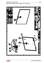
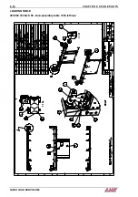
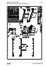
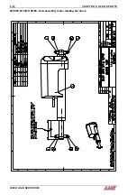
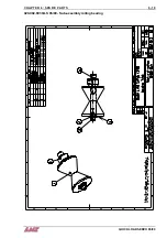
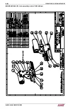
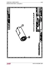
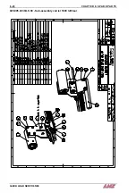
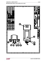
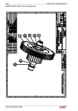
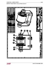
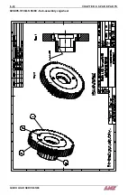
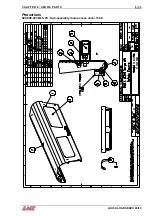
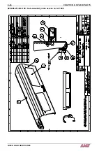
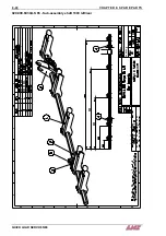
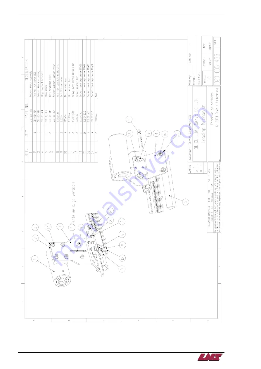
020.005.433 QLS 80 - Sub-assembly carrier 1600 left/rear 


QUICK LOAD SERVO 65/80 

Содержание Quick Load Servo 65

Страница 1: ...Troubleshooting manual ENG 9 020 01 ANG ...

Страница 2: ...e without lathe auto mode 1 17 A28 Parts counting parity error by M code quantity and automatic part counting 1 18 A30 Bar stock loading error 1 19 A41 Servo amplifier PLC communication fault 1 20 A42 Servo drive alarm 1 21 A43 Amplifier battery low 1 22 A44 Servo motor not ready 1 23 A45 Servo motor positioning error during sequence 1 24 A50 Servo amplifier firmware not compatible with PLC 1 25 B...

Страница 3: ...apter 6 6 1 Spare Parts 6 1 Recommended Spare Parts List 6 2 Mechanical Assemblies 6 3 Base 6 11 Crossing Slide 6 20 Loading Mechanism 6 23 Protections 6 33 Foot 6 35 Loading Magazine 6 37 Retraction 6 42 Pusher 6 45 Accessories Options 6 51 Floor Plans 6 53 QUICK LOAD SERVO 65 80 ...

Страница 4: ...feeder When an error occurs an alarm message is generated on the remote control station Also provided are some possible causes as to why the error has occurred This chapter discusses every alarm that the bar feed may generate explains the possible causes suggests a few tips and procedures of how to correct the problem ...

Страница 5: ...M 3 4 838 Diameter selection fingers motor QS 1 4 242 Main disconnect switch SQ 1 4 391 Proximity switch loading table in lower position SQ 3 4 474 Positioning optical cell SQ 4 4 391 Proximity switch diameter selection fingers in origin position SQ 5 4 391 Pusher in home position switch SQ 10 4 763 Cover closed safety switch SQ 11 4 763 Magazine cover closed safety switch SQ 12 4 763 Retraction s...

Страница 6: ... problem is generated anytime there is an open in the safety circuit Solution In the working screen press the key on the remote control Press the key corresponding to Page Down until the INPUTS page is displayed Case Input Solution 1 K1 0 Check the emergency buttons state on the bar feeder and the lathe Check the PLC connection Check the wiring according to the electrical diagram Press the STOP bu...

Страница 7: ...s generated when the main access cover on the bar feeder is open exposing automated mechanical parts Solution In the working screen press the key on the remote control Press the key corresponding to Page Down until the INPUTS page is displayed Case Input Solution 1 SQ10 0 Close the cover Check the SQ10 switch is adjusted correctly 2 SQ10 1 Press the STOP button on the remote control to reset the a...

Страница 8: ...nput I18 SQ11 The problem is generated when the protection grid on the bar feeder is open or if the switch is defective Solution In the working screen press the key on the remote control Press the key corresponding to Page Down until the INPUTS page is displayed Case Input Solution 1 SQ11 0 Close the protection grid Check that the SQ11 switch is adjusted correctly 2 SQ11 1 Press the STOP button on...

Страница 9: ... input I19 SQ12 The problem is generated when the bar feeder is retracted in reduction tube change position or if the retraction system is not locked Solution In the working screen press the key on the remote control Press the key corresponding to Page Down until the INPUTS page is displayed Case Input Solution 1 SQ12 0 Set the bar feeder back in operating position and lock it 2 SQ12 1 Press the S...

Страница 10: ...nd before the loading table goes up or down The problem is generated when the switch is obstructed defective or if any obstacle is detected in the switch detecting range Solution In the working screen press the key on the remote control Press the key corresponding to Page Down until the INPUTS page is displayed Case Input Solution 1 SQ3 1 Remove any obstacle in the detecting range of the switch Ch...

Страница 11: ... encoder reads the home position 0 0 mm The problem is generated when the switch is defective or mis adjusted Solution In the working screen press the key on the remote control Press the key corresponding to Page Down until the INPUTS page is displayed Case Input Solution 1 SQ5 1 Press the STOP button on the remote control to reset the alarm 2 SQ5 0 Check that the SQ5 switch is adjusted correctly ...

Страница 12: ...sary quantity of pulses to reach the requested position with in the delay of 8 seconds when the loading table goes down and the PLC does not detect the input I24 SQ1 with in the delay of 8 seconds Solution In the working screen press the key on the remote control Press the key corresponding to Page Down until the INPUTS page is displayed Case Input Solution 1 SQ1 1 Press the STOP button on the rem...

Страница 13: ...ed position within 6 seconds when the diameter adjustment fingers return towards the origin when the PLC does not detect the input I27 SQ4 within 6 seconds Solution In the working screen press the key on the remote control Press the key corresponding to Page Down until the INPUTS page is displayed Case Input Solution 1 SQ4 1 Press the STOP button on the remote control to reset the alarm 2 SQ4 0 Ch...

Страница 14: ...g Solution Press the STOP key on the remote control to clear the message and reset the alarm Press the key corresponding to the MENU Choose the SERVICE item Press the key corresponding to ENTER to confirm From the service menu choose the BAR FEEDER SETUP item Press the key corresponding to ENTER to confirm Press the key corresponding to PAGE DOWN as many times as necessary to display the text MAXI...

Страница 15: ...INTERRUPTED DURING LOADING CYCLE A22 Description The Signal A2 lathe in automatic mode interrupted during loading cycle alarm is generated if the signal I41 A2 is interrupted in the loading cycle Solution Verify the lathe bar feeder connection Verify the wiring of the signal A2 Check the lathe programming QUICK LOAD SERVO 65 80 ...

Страница 16: ...shed near the back of the clamping device Then the spindle rotates very slowly while the bar feeder pushes the bar stock against the clamping device until the bar shape corresponds with the clamping device s shape goes through and reaches the top cut position After 20 attempts this alarm is generated Solution Press the STOP key on the remote control to clear the message and reset the alarm Remove ...

Страница 17: ...Description The safety time for top cut positioning elapsed alarm when the bar stock is in loading cycle for top cut if the top cut position is not reached within 5 minutes Solution Press the STOP button on the remote control to reset the alarm Restart the automatic cycle on bar feeder and lathe QUICK LOAD SERVO 65 80 ...

Страница 18: ... A25 Description The Lathe did not resume its production cycle alarm occurs when the bar feeder does not detect the clamping device signal I40 A1 within the minute following the reach of the top cut positioning Solution Press the STOP button on the remote control to reset the alarm Restart the automatic cycle on bar feeder and lathe ...

Страница 19: ...device closed prior to completing the feed out alarm occurs whenever the clamping device closing signal is detected before the value entered in parameter overall part length feed out has been reached Solution Check that the clamping device is closing correctly Check that the signal Clamping device closing is correctly interfaced and programmed QUICK LOAD SERVO 65 80 ...

Страница 20: ...E IN AUTO MODE A27 Description The Clamping device opened during production cycle without lathe auto mode alarm occurs when the PLC detects the clamping device opening signal I40 A1 while the bar feeder in auto cycle and lathe not in auto mode input I41 A2 Solution Press the STOP button on the remote control to reset the alarm Restart the automatic cycle on bar feeder and lathe ...

Страница 21: ...ion The Parts counting parity error by M code quantity and automatic part counting alarm occurs whenever clamping device openings quantity does not match the value number of clamping device openings while the input I43 A4 is activated Solution Press the STOP button on the remote control to reset the alarm Restart the automatic cycle of the bar feeder and the lathe QUICK LOAD SERVO 65 80 ...

Страница 22: ...RONG SET UP A30 Description The Bar stock loading error alarm is generated when no material is detected in the guidance zone and the PLC detects the input I25 SQ3 when the loading finger is at the most advanced position That means that there is no material on the loading table Solution Load new material on the magazine ...

Страница 23: ...fier and the amplifier does not confirm it sending back a checksum The problem occurs if sent data do not correspond to received data the servo amplifier does not answer within 10 seconds during starting the bar feeder PLC and servo amplifier parameters do not correspond Solution Verify the PLC servo amplifier connection F110 Verify the PLC power supply 24V DC Power variations may influence the PL...

Страница 24: ...TORE MAIN POWER A42 Description The Servo drive alarm alarm occurs whenever the servo amplifier generates an alarm Solution Turn off main power wait 2 seconds and restore main power If the problem persists find the displayed alarm number on the servo amplifier and refer to the Mitsubishi servo amplifier alarm list in the manual ...

Страница 25: ...TERY LOW REPLACE BATTERY IMMEDIATELY A43 Description The Amplifier battery low alarm occurs whenever the voltage of the integrated amplifier battery is too low Solution Replace the battery as soon as possible refer to the instruction manual QUICK LOAD SERVO 65 80 ...

Страница 26: ...tor to set it in servo lock position If the servo amplifier does not recognize the signal within 3 seconds this alarm is generated Solution Verify the CN1B cable connection to the amplifier Verify that the output O52 is activated when the automatic or manual cycle is started Verify that the K1 relay is active the input I16 must be active If the problem persists please contact LNS America Inc ...

Страница 27: ...o a defined limit Over this point the PLC stops the pushing and activates this alarm Solution Press the STOP button on the remote control to reset the alarm Verify any mechanical obstacle preventing the bar stock to feed out Verify the bar stock diameter It must correspond to the entered value in the remote control display applications Verify the alignment between the lathe and the bar feeder This...

Страница 28: ...h PLC SERVO AMPLIFIER FIRMWARE NOT COMPATIBLE WITH PLC REPLACE SERVO AMPLIFIER A50 Description Only an adapted firmware to our servo motor will work Otherwise the Servo amplifier firmware not compatible with PLC alarm is generated Solution Please contact LNS AMERICA INC to update your firmware ...

Страница 29: ...k under the measuring cell SQ3 7 Calculation 8 The loading flag pushes the bar stock behind the clamping device 9 The loading flag pushes the bar stock to the EOB or to the top cut position 10 Production cycle with loading table in upper position 11 The loading flag moves back to home position 12 The loading table starts moving down 13 The pusher moves to the bar stock rear 14 The pusher moves the...

Страница 30: ...use Section 11 2 2 Switch on servo on signal Servo motor shaft is not servo locked is free 1 Check the display to see if the servo amplifier is ready to operate 2 Check the external I O signal indication to see if the servo on SON signal is ON 1 Servo on signal is not input Wiring mistake 2 24VDC power is not supplied to COM Section 6 6 of the Mitsubishi Servo Amplifier manual Rotation ripples spe...

Страница 31: ... 0 0 Memory error 3 AL 1A 1 1 0 Motor combination error AL 20 1 1 0 Encoder error 2 AL 24 1 0 0 Main circuit error AL 25 1 1 0 Absolute position erase AL 30 0 0 1 Regenerative error AL 31 1 0 1 Overspeed AL 32 1 0 0 Overcurrent AL 33 0 0 1 Overvoltage AL 35 1 0 1 Command pulse frequency error AL 37 0 0 0 Parameter error AL 45 0 1 1 Main circuit device overheat AL 46 0 1 1 Servo motor overheat AL 5...

Страница 32: ... used to refer to the cause Display Name Definition Cause Action 1 Power supply voltage is low 2 There was an instantaneous control power failure of 60ms or longer 3 Shortage of power supply capacity caused the power supply voltage to drop at start etc 4 Power was restored after the bus voltage had dropped to 200VDC Main circuit power switched on within 5s after it had switched off Review the powe...

Страница 33: ...ome position setting again 2 Battery voltage low Absolute position data in error 3 Battery cable or battery is faulty Change battery Always make home position setting again AL 25 Absolute position erase Power was switched on for the first time in the absolute position detection system 4 Super capacitor of the absolute position encoder is not charged After leaving the alarm occurring for a few minu...

Страница 34: ...overcurrent detection circuit to misoperate Take noise suppression measures 1 Lead of built in regenerative brake resistor or regenerative brake option is open or disconnected 1 Change lead 2 Connect correctly 2 Regenerative transistor faulty Change servo amplifier 3 Wire breakage of built in regenerative brake resistor or regenerative brake option 1 For wire breakage of built in regenerative brak...

Страница 35: ... Install limit switches 4 Wrong connection of servo motor Servo amplifier s output terminals U V W do not match servo motor s input terminals U V W Connect correctly AL 50 Overload 1 Load exceeded overload protection characteristic of servo amplifier Load ratio 300 2 5s or more Load ratio 200 100s or more 5 Encoder faulty Checking method When the servo motor shaft is rotated with the servo off the...

Страница 36: ...f the deviation counter exceeded the encoder resolution 10 pulse 8 Wrong connection of servo motor Servo amplifier s output terminals U V W do not match servo motor s input terminals U V W Connect correctly 1 Communication cable breakage Repair or change communication cable 2 Communication cycle longer than parameter No 23 setting Set correct value in parameter AL 8A Serial communication time out ...

Страница 37: ...ses Do not enter command pulse after clearing of droop pulses AL 96 Home position setting warning Home position setting could not be made 3 Creep speed high Reduce creep speed 1 Software limit was set within actual operation range Set parameter No 48 to 51 correctly 2 Point table of position data in excess of software limit was executed Set point table correctly AL 98 Software limit warning Softwa...

Страница 38: ... quick changeovers and the capability for unmanned operation this unit is not flawless A list of common issues that have been documented by service technicians and problems relayed back from customers has been compiled in this manual This chapter discusses the most common problems that have been observed Along with each problem a brief description is given as well as quick reference charts of symp...

Страница 39: ...terial Aluminum should not generate any vibrations Steel should not generate any vibrations Inox steel can generate some vibrations Brass copper and other soft materials can generate some vibrations without affecting the machined part Test with standard steel or aluminum bar stock Material profile Round bars should rotate without noise Profiled bars should generate acceptable noise vibration Bar s...

Страница 40: ...eared Press the STOP key on the remote control station to clear the message and reset the alarm Check that nothing can prevent the bar stock from moving forward Check that the correct bar stock diameter is entered for the parameter Cause Solution Hitting back of spindle Check that the correct bar stock diameter is entered for the parameter Check that the correct spindle reduction tube is installed...

Страница 41: ...eed with help of the turret This application can be selected when either a pull to close or push to close type clamping system is installed but must always be selected when a push to close type clamping system is installed This is due to the bar stock moving forward as the draw tube pushes forward to close the clamping device Parameters related to clamping device located in 4 Miscellaneous Functio...

Страница 42: ...acing operation on the bar stock during top cut verify that the end of the bar stock is in the same location as if a part was cut off after the cut off or facing operation is complete Part feed out too short Verify that the correct value is entered into the Input overall part length parameter If using a pull to close type clamping system ensure that the time entered into the Time for clamping devi...

Страница 43: ......

Страница 44: ...K LOAD SERVO 65 80 3 1 Chapter 3 Procedures he following chapter includes simple step by step procedures for mechanical adjustments replacing damaged or faulty components and to resolve other issues related to the bar feeder T ...

Страница 45: ...small as possible Note If obstacles prevent the bar feed from being positioned within 200 mm of the back of the spindle an extension will be required Step 2 Level the bar feed in the x and y axis using a torpedo level The level can be placed on the linear belt rail to verify the y axis and on the retract rails to verify the x axis Use the leveling screws on the retract to adjust unit to level Leve...

Страница 46: ...ed in the slots on the base of the unit 6 each side This will allow the unit to be adjusted up and down Step 4 Using the central jackscrew adjust the unit so that the pusher is centered up and down at the back of the spindle Make sure that the unit raises or lowers uniformly Central jackscrew ...

Страница 47: ...the rear of the spindle and the front of the bar feed when centering to the rear of the collet Once the pusher is centered at the back of the collet recheck the alignment at the back of the spindle by pulling the pusher back Continue until the pusher is centered at the rear of the spindle and at the rear of the collet Step 7 Once the bar feed has been aligned anchor it using the 4 anchor bolts sup...

Страница 48: ...ing table and verify that it can be loaded into the spindle of the Note If the bar hits side to side the alignment will have to be adjusted Procedure complete A Step 10 Once the power has been hooked up the bar feed must be calibrated Refer to Calibration of the Lo Table procedure After calibrating the bar feed return to this procedure and move on to Step 11 for the final alignment For final align...

Страница 49: ... Step 1 Open the main access cover Step 2 Pull the carrier away from the home position Step 3 Press the pusher adapter locking unlocking finger toward the front of the bar feeder then turn the finger a of a turn clockwise The finger must stay locked in forward position Pull the pusher towards the bar feeder front but don t extract it completely out of the carrier QUICK LOAD SERVO 65 80 ...

Страница 50: ...ew pusher body with the corresponding shaft Step 8 Put the corresponding white bushing on the pusher Insert the front end of the pusher through the front of the bar feed first then slide the pusher adapter through the carrier so that it is flush on the right hand side of the carrier Step 9 When the pusher adapter is in place in the carrier turn the finger of a turn back counter clockwise The finge...

Страница 51: ...3 CHAPTER 3 PROCEDURES 3 8 Step 10 Slide back the carrier to the home position Close the main access cover Procedure complete QUICK LOAD SERVO 65 80 ...

Страница 52: ...en the main access cover Step 2 Make sure the carrier is in home position Step 3 In the middle of the linear rail measure the belt vertical displacement from the belt to the rail Don t force it This displacement must be approx 20 mm If necessary modify the belt tension with the belt tensioner located at the front of the bar feed Step 4 Once the tension is set close the main access cover Procedure ...

Страница 53: ...Nylon bushing is the mechanical home position Step 3 Adjust the SQ5 proximity switch position just far enough to get a strong signal from the switch approx 0 5 mm and tighten down Any slight movement forward of the carrier should deactivate the proximity sensor 0 5 mm Step 4 Close the main access cover Step 5 Press the STOP key on the remote control to clear any alarm Reference the bar feed see Re...

Страница 54: ...In manual mode move up the loading table if the adjustment fingers don t move run the carrier flag forward to the end and then back to the home position drop the table down and then repeat this step Note If the bar is not picked up by the table the switch is set too high Set it a little lower and repeat points 2 and 3 In upper position the bar stock should touch the table stops and the selection f...

Страница 55: ...e main access cover Step 4 Place a piece or bar stock of 6 mm or smallest diameter stock available into the channel Note the stock must be straight to obtain the ideal adjustment Step 5 Push the stock up so that it is sticking out the front of the bar feeder Turn the gain adjustment clockwise on the measuring cell to the max position A ticking noise marks the end of the adjusting range Step 6 Loos...

Страница 56: ...e gain adjustment clockwise until the sensor detects the bar a Step 9 emove the material from the channel and close the main access cover ess Cover Open alarm Procedure adjusting range F yellow LED will illuminate once the bar is detected Once the sensor detects the bar continue to turn the gain clockwise another turn R Step 10 Press the STOP key on the remote control station to clear the Main Acc...

Страница 57: ...s as necessary to display the text PUSHER REVERSE DISTANCE Step 4 With the up down keys select 2 Press on the key corresponding to ENTER Step 5 Exit the menu by pressing on the key corresponding to ESC Enter value In automatic mode after clamping device closing the pusher moves back by the entered value Step 1 Press on the key corresponding to MANUAL MODE Step 2 In manual mode raise the loading ta...

Страница 58: ...SERVICE Step 2 Press on the key corresponding to PAGE DOWN as many times as necessary until this text appears Select option 2 using the up arrow key Once 2 is selected press and hold ENTER for 2 3 seconds The screen will then return to the home page REQUEST FOR REFERENCE POINT 1 NO 2 YES ESC ENTER Step 3 Press on the key corresponding to MANUAL MODE LOADING CHANNEL IN AN INTERMEDIATE POSITION F1 M...

Страница 59: ...e PLC waits to detect the proximity switch SQ5 and the servo amplifier looks for the torque to build up after hitting the mechanical stop Once the home position is set the HOME PAGE will reappear on the remote control station REFERENCE POINT POSITIONING IN PROGRESS Procedure complete QUICK LOAD SERVO 65 80 ...

Страница 60: ... to ENTER Step 4 In the service menu select the menu BAR FEED SETUP then press on the key corresponding to ENTER Step 5 Press on the key corresponding to PAGE DOWN until the text NUMBER OF PULSES FOR TABLE CENTERING CALIBRATION Press on any arrow key Step 6 Enter with the up down and left right keys the password 2534 then press on the key corresponding to ENTER Step 7 Enter with the up down keys t...

Страница 61: ......

Страница 62: ...ation inter PLC holds a backup program for the Quick Load Servo 65 80 if at anytime there has or any error has occurred in the user program In addition it automatically backs up face parameters that have been set for the most recent application being run Following a few systematic procedures is all it takes to be up and running with the most up to date software or restoring lost PLC programs and o...

Страница 63: ...APTER 4 SOFTWARE 4 2 Software PLC Versions To find the LNS software version In the working menu press the key on the remote control Press the Page Down key to read more information QUICK LOAD SERVO 65 80 ...

Страница 64: ...dure Step 1 In the electrical cabinet open the PLC cover Step 2 Insert the card containing the new software in the M1 labeled bay A chamfer avoids any bad insertion Step 3 With a sharp object press on the little button labeled Run Halt for approx 3 seconds until the LED located at its left blinks ...

Страница 65: ... software is loaded This operation takes max 10 seconds When the barfeed has saved all the parameters it is operational again Step 5 Take out the card containing the software Close the PLC cover and the electrical cabinet Procedure Complete QUICK LOAD SERVO 65 80 ...

Страница 66: ...the electrical cabinet open the PLC cover Step 2 Take the battery support out of the bay labeled BATT Step 3 Replace the battery with an identical type Check that the battery is in the right direction Step 4 Insert back the battery support in its bay Close the PLC cover and the electrical cabinet Procedure Complete ...

Страница 67: ......

Страница 68: ...and prolong its useful life Following a few simple steps can be extremely helpful and takes relatively no time at all The list of maintenance procedures has been broken down into two groups determined by the frequency with which each procedure should be followed however some items should be checked more often depending on the operating environment that the equipment is exposed P ...

Страница 69: ...ause chips and other particles can become lodged in sensitive areas and can impede the proper operation of the bar feeder Annual Maintenance Check the PLC battery The PLC backup battery saves the PLC program in case of any power failure The battery used in the controller is a non rechargeable 3VDC Lithium CD2032 battery Over time the battery will slowly discharge and an alarm message will appear o...

Страница 70: ...VO 65 80 6 1 Chapter 6 Spare Parts hen ordering parts the following information will be needed to ensure better customer support Bar feeder type Bar feeder serial number located on the sub base W Bar stock diameter Lathe type brand model ...

Страница 71: ...nimize downtime Keeping an inventory can also be very cost effective since shipping costs can escalate immensely especially in cases where rush delivery is necessary Designation Article No Description QS 1 4 242 Main disconnect switch SQ 1 4 391 Proximity switch loading table in lower position SQ 3 4 474 Positioning optical cell SQ 4 4 391 Proximity switch diameter selection fingers in origin posi...

Страница 72: ...CHAPTER 6 SPARE PARTS QUICK LOAD SERVO 65 80 6 3 Mechanical Assemblies 020 000 011 QLS 65 Machine assembly left rear longitudinal retraction ...

Страница 73: ...CHAPTER 6 SPARE PARTS 6 4 020 000 021 QLS 65 Machine assembly left rear transversal retraction QUICK LOAD SERVO 65 80 ...

Страница 74: ...CHAPTER 6 SPARE PARTS QUICK LOAD SERVO 65 80 6 5 020 000 031 QLS 65 Machine assembly left front longitudinal retraction ...

Страница 75: ...CHAPTER 6 SPARE PARTS 6 6 020 000 041 QLS 65 Machine assembly left front transversal retraction QUICK LOAD SERVO 65 80 ...

Страница 76: ...CHAPTER 6 SPARE PARTS QUICK LOAD SERVO 65 80 6 7 020 000 111 QLS 80 Machine assembly left rear longitudinal retraction ...

Страница 77: ...CHAPTER 6 SPARE PARTS 6 8 020 000 121 QLS 80 Machine assembly left rear transversal retraction QUICK LOAD SERVO 65 80 ...

Страница 78: ...CHAPTER 6 SPARE PARTS QUICK LOAD SERVO 65 80 6 9 020 000 131 QLS 80 Machine assembly left front longitudinal retraction ...

Страница 79: ...CHAPTER 6 SPARE PARTS 6 10 020 000 141 QLS 80 Machine assembly left front transversal retraction QUICK LOAD SERVO 65 80 ...

Страница 80: ...CHAPTER 6 SPARE PARTS QUICK LOAD SERVO 65 80 6 11 Base 020 001 213 QLS 65 Base left rear Table base fingers assembled ...

Страница 81: ...CHAPTER 6 SPARE PARTS 6 12 020 001 243 QLS 65 Base left front Table base fingers assembled QUICK LOAD SERVO 65 80 ...

Страница 82: ...CHAPTER 6 SPARE PARTS QUICK LOAD SERVO 65 80 6 13 020 001 313 QLS 80 Base left rear Table base fingers assembled ...

Страница 83: ...CHAPTER 6 SPARE PARTS 6 14 020 001 343 QLS 80 Base left front Table base fingers assembled QUICK LOAD SERVO 65 80 ...

Страница 84: ...CHAPTER 6 SPARE PARTS QUICK LOAD SERVO 65 80 6 15 020 001 603 QLS 65 80 Sub assembly electrical cabinet door ...

Страница 85: ...CHAPTER 6 SPARE PARTS 6 16 LOADING TABLE 020 002 103 QLS 65 Sub assembly table 1300 left rear QUICK LOAD SERVO 65 80 ...

Страница 86: ...CHAPTER 6 SPARE PARTS QUICK LOAD SERVO 65 80 6 17 020 002 123 QLS 80 Sub assembly table 1600 left rear ...

Страница 87: ...CHAPTER 6 SPARE PARTS 6 18 020 002 613 QLS 65 80 Sub assembly motor loading bar stock QUICK LOAD SERVO 65 80 ...

Страница 88: ...CHAPTER 6 SPARE PARTS QUICK LOAD SERVO 65 80 6 19 020 002 803 QLS 65 80 Sub assembly rolling bearing ...

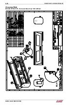
Страница 89: ...CHAPTER 6 SPARE PARTS 6 20 Crossing Slide 020 004 103 QLS 65 Sub assembly body 1300 left rear QUICK LOAD SERVO 65 80 ...

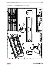
Страница 90: ...CHAPTER 6 SPARE PARTS QUICK LOAD SERVO 65 80 6 21 020 004 123 QLS 80 Sub assembly body 1600 left rear ...

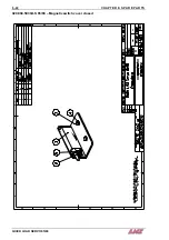
Страница 91: ...CHAPTER 6 SPARE PARTS 6 22 020 004 503 QLS 65 80 Magnetic switch cover closed QUICK LOAD SERVO 65 80 ...

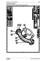
Страница 92: ...CHAPTER 6 SPARE PARTS QUICK LOAD SERVO 65 80 6 23 Loading Mechanism 020 005 103 QLS 65 80 Sub assembly centering bearing ...

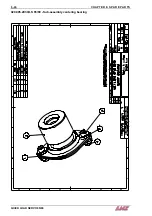
Страница 93: ...CHAPTER 6 SPARE PARTS 6 24 020 005 203 QLS 65 80 Sub assembly centering bearing QUICK LOAD SERVO 65 80 ...

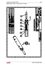
Страница 94: ...CHAPTER 6 SPARE PARTS QUICK LOAD SERVO 65 80 6 25 020 005 303 QLS 65 80 Locking pusher assembled ...

Страница 95: ...CHAPTER 6 SPARE PARTS 6 26 020 005 403 QLS 65 Sub assembly carrier 1300 left rear QUICK LOAD SERVO 65 80 ...

Страница 96: ...CHAPTER 6 SPARE PARTS QUICK LOAD SERVO 65 80 6 27 020 005 413 QLS 65 80 Locking block ...

Страница 97: ...CHAPTER 6 SPARE PARTS 6 28 020 005 433 QLS 80 Sub assembly carrier 1600 left rear QUICK LOAD SERVO 65 80 ...

Страница 98: ...CHAPTER 6 SPARE PARTS QUICK LOAD SERVO 65 80 6 29 020 005 603 QLS 65 80 Sub assembly servo motor ...

Страница 99: ...CHAPTER 6 SPARE PARTS 6 30 020 005 703 QLS 65 80 Sub assembly drive QUICK LOAD SERVO 65 80 ...

Страница 100: ...CHAPTER 6 SPARE PARTS QUICK LOAD SERVO 65 80 6 31 020 005 713 QLS 65 80 Sub assembly tensioner ...

Страница 101: ...CHAPTER 6 SPARE PARTS 6 32 020 005 723 QLS 65 80 Sub assembly cogwheel QUICK LOAD SERVO 65 80 ...

Страница 102: ...CHAPTER 6 SPARE PARTS QUICK LOAD SERVO 65 80 6 33 Protections 020 006 203 QLS 65 Sub assembly main access cover 1300 ...

Страница 103: ...CHAPTER 6 SPARE PARTS 6 34 020 006 213 QLS 80 Sub assembly main access cover 1600 QUICK LOAD SERVO 65 80 ...

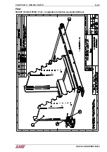
Страница 104: ...CHAPTER 6 SPARE PARTS QUICK LOAD SERVO 65 80 6 35 Foot 020 007 103 QLS 65 80 Foot longitudinal retraction assembled left rear ...

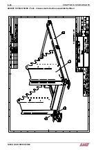
Страница 105: ...CHAPTER 6 SPARE PARTS 6 36 020 007 133 QLS 65 80 Foot transversal retraction assembled left rear QUICK LOAD SERVO 65 80 ...

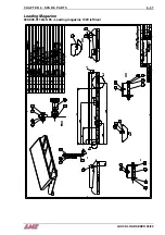
Страница 106: ...CHAPTER 6 SPARE PARTS QUICK LOAD SERVO 65 80 6 37 Loading Magazine 020 009 011 QLS 65 Loading magazine 1300 left rear ...

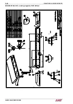
Страница 107: ...CHAPTER 6 SPARE PARTS 6 38 020 009 031 QLS 80 Loading magazine 1600 left rear QUICK LOAD SERVO 65 80 ...

Страница 108: ...CHAPTER 6 SPARE PARTS QUICK LOAD SERVO 65 80 6 39 020 009 313 QLS 65 80 Diameter selection setup assembled ...

Страница 109: ...CHAPTER 6 SPARE PARTS 6 40 020 009 603 QLS 65 Sub assembly shaft 1300 left rear QUICK LOAD SERVO 65 80 ...

Страница 110: ...CHAPTER 6 SPARE PARTS QUICK LOAD SERVO 65 80 6 41 020 009 643 QLS 80 Sub assembly shaft 1600 left rear ...

Страница 111: ...CHAPTER 6 SPARE PARTS 6 42 Retraction 020 010 103 QLS 65 80 Retraction left rear assembled QUICK LOAD SERVO 65 80 ...

Страница 112: ...CHAPTER 6 SPARE PARTS QUICK LOAD SERVO 65 80 6 43 020 010 403 QLS 65 80 Sub assembly retraction wheel ...

Страница 113: ...CHAPTER 6 SPARE PARTS 6 44 020 010 603 QLS 65 80 Magnetic switch retraction QUICK LOAD SERVO 65 80 ...

Страница 114: ...CHAPTER 6 SPARE PARTS QUICK LOAD SERVO 65 80 6 45 Pusher 020 011 013 6 QLS 65 Assembly pusher ø1 4 ...

Страница 115: ...CHAPTER 6 SPARE PARTS 6 46 020 011 013 12 QLS 65 Assembly pusher ø12 QUICK LOAD SERVO 65 80 ...

Страница 116: ...CHAPTER 6 SPARE PARTS QUICK LOAD SERVO 65 80 6 47 020 011 013 20 QLS 65 Assembly pusher ø20 ...

Страница 117: ...CHAPTER 6 SPARE PARTS 6 48 020 011 023 6 QLS 80 Assembly pusher ø1 4 QUICK LOAD SERVO 65 80 ...

Страница 118: ...CHAPTER 6 SPARE PARTS QUICK LOAD SERVO 65 80 6 49 020 011 023 12 QLS 80 Assembly pusher ø12 ...

Страница 119: ...CHAPTER 6 SPARE PARTS 6 50 020 011 023 20 QLS 80 Assembly pusher ø20 QUICK LOAD SERVO 65 80 ...

Страница 120: ...CHAPTER 6 SPARE PARTS QUICK LOAD SERVO 65 80 6 51 Accessories Options 020 013 112 QLS 65 80 Orientation kit for square stocks ...

Страница 121: ...CHAPTER 6 SPARE PARTS 6 52 020 013 033 QLS 65 80 Front protection cover 300 mm QUICK LOAD SERVO 65 80 ...

Страница 122: ...CHAPTER 6 SPARE PARTS QUICK LOAD SERVO 65 80 6 53 Floor Plans 020 015 011 Assembly QLS 65 left rear longitudinal retraction ...

Страница 123: ...CHAPTER 6 SPARE PARTS 6 54 020 015 021 Assembly QLS 65 left rear transversal retraction QUICK LOAD SERVO 65 80 ...

Страница 124: ...CHAPTER 6 SPARE PARTS QUICK LOAD SERVO 65 80 6 55 020 015 031 Assembly QLS 65 left front longitudinal retraction ...

Страница 125: ...CHAPTER 6 SPARE PARTS 6 56 020 015 041 Assembly QLS 65 left front transversal retraction QUICK LOAD SERVO 65 80 ...

Страница 126: ...CHAPTER 6 SPARE PARTS QUICK LOAD SERVO 65 80 6 57 020 015 111 Assembly QLS 80 left rear longitudinal retraction ...

Страница 127: ...CHAPTER 6 SPARE PARTS 6 58 020 015 121 Assembly QLS 80 left rear transversal retraction QUICK LOAD SERVO 65 80 ...

Страница 128: ...CHAPTER 6 SPARE PARTS QUICK LOAD SERVO 65 80 6 59 020 015 131 Assembly QLS 80 left front longitudinal retraction ...

Страница 129: ...CHAPTER 6 SPARE PARTS 6 60 020 015 141 Assembly QLS 80 left front transversal retraction QUICK LOAD SERVO 65 80 ...

Отзывы: