ENG
| Instruction Manual
INSTALLATION
LK 440 EasyHeat should be placed indoors/under a roof and fully
protected from rain.
The integrated safety package including automatic air-bleed valve,
safety valve and connecting hoses, must be installed as shown in the
product diagram (see above). Relevant building standards and hot
water installation standards must be adhered to.
The safety valve’s outlet’s functioning must be ensured in the appro-
priate manner; refer to current hot water installation standards. No
thermometer is included in the standard kit. However, a thermometer
should be mounted on the pipe after the boiler.
The heating system must be arranged so that there is always a
flow through the cassette. Check to see that one or more of the
heating loops are always open.
SWITCHING ON
Before switching on, check to see that the heating system is filled
with water, air-bled and that the system’s operating pressure is
sufficient.
Check to see that the circulation pump is running by listening to
and testing the various pump speed settings.
THERMOSTAT OPERATION
Temperature regulation is via the boiler’s operational thermostat
(constant output temperature). The thermostat can be set up to a
maximum of 60 ºC.
Monitor the output temperature by means of a thermometer and
compare it to the set temperature.
CIRCULATION
For setting up the circulation pump, see separate instruction
”Grundfos UPM3 Auto 15/70”. Note that the pump is advanta-
geously set to work with constant pressure and that this must be
set manually according to separate instructions.
OVERHEATING PROTECTION
LK 440 EasyHeat is provided with built in overheating protection,
which cuts off the power at approx. 70 ºC.
To reset the overheating protection function, press button (12).
Resetting is possible after the boiler has cooled down to approx. 60
ºC. In the event of a repeated overheating, determine the cause of
the fault and fix it before restarting.
TRIP SWITCH, CIRCULATION PUMP
The circulation pump is protected by a 10 A Trip Switch (13). In the
event of the fuse tripping out, determine the cause of the fault and
fix it before restarting.
SAFETY VALVE
The safety valve must be tested at start-up and then at set inter-
vals 2-3 times per year. CAUTION: Take care when testing as the
out-flowing water/steam can cause scald injuries.
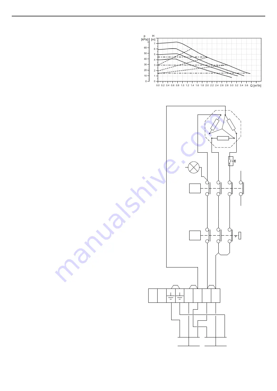
ELECTRIC CONNECTION DIAGRAM
PUMP GRAPH
11
12
21
22
31
32
41
42
0-60°C
T
11
12
21
22
31
32
STB
80°
1
3 kW
N N L L
3x1,5mm
2
1m
3x0,75mm
2
0,2m
Stickprop
cirkpump
N
Socket
Pump
2
www.lkarmatur.com


