


Clean Blade Boost v1.0
4
General guideline for components
Capacitors: All values under 1nF should be ceramic disks. From 1nF up to 1uF should be SMF
or MKT (foil/metal film capacitors) and over 1uF use electrolyte caps 35V+ rated and watch
out for polarity!
Resistors: use 1% metal film for the best results.
Socket all transistors and the voltage regulator. This way you can easily mod them or replace
them if they brake.
Orientation of the transistors: the white stripe on the PCB indicates where the flat side of the
transistor should be.
General building tips
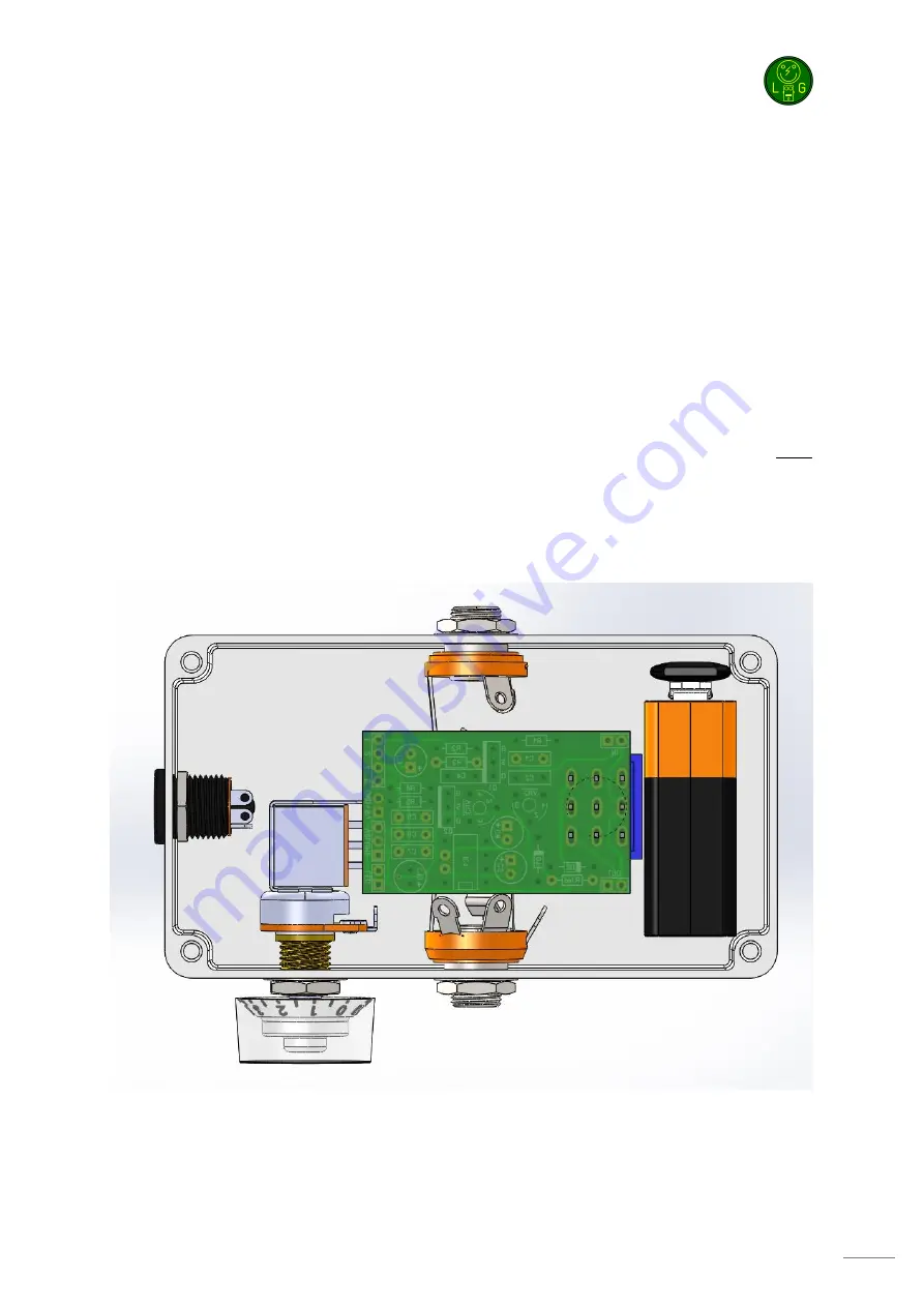
Before starting, do note that height might become an issue during this build. Try to solder everything
as close to the PCB as possible. It might be a good idea to solder the transistors to the board after
you selected the best ones to your taste. If you want to keep them socketed then you’ll need to bend
them. Same goes for the electrolyte capacitors. So examine the maximum height of the components
before starting your build. Also note that the 3PDT should can be placed on both the bottom as the
top side of the PCB. The components should be placed on the top side. By default it is advised to
mount the 3PDT on the bottom side, however If your enclosure is very small it might be a good idea
to mount the 3PDT on the topside. Decide this before starting your build.
Soldering this board can be complicated for some people since the solder pads can be very close
together. Use a magnifying glass to make the job easier.
Start by soldering the resistors (not yet VR2 and VR3) and the diodes. Now solder the capacitors
starting with the smallest. Next, solder the sockets for the transistors and voltage regulator. For the
transistors you can buy a 20 pin SIL socket and cut of the pins you need.
Содержание Clean Blade Boost
Страница 1: ...Clean Blade Boost Building instructions V1 0...
Страница 8: ...Clean Blade Boost v1 0 8 Schematic...