background image


TME-EPIC-HURQM-R2V1.docx 

Revision 2.1 


Page 52 of 52 


6


Troubleshooting 

First steps if the board does not boot: 


Check the status LEDs on the board. Are all voltages properly available? 


Check the power connectors to the board, monitor and additional devices. 


Are all cables plugged on the correct connector and in the correct orientation?  The board may not boot 

if some of the cables are not plugged in correctly! 


Check the power supply. Is the supply voltage correct for the board? If you are not sure, read the 

manual. Try plugging in a different power supply or multi-meter to check the power a wrong supply 

voltage can easily FRY a computer and other electrical devices. 


Is your display ok?  Is the monitor powered on?  Is the monitor's video cable plugged into the video 

connector?  Double-check the brightness and contrast settings. Plug the monitor into another 
computer if possible to verify the monitor is not the problem. 


Remove all additional devices from the system.  Only the processor board, power supply, monitors and 
the keyboard should remain in the system. 


Assure your cooling measures work correctly and keep the processor at a reasonable temperature. 


If all else has failed, replace the CPU Board itself.  


If system comes up then load at first the OPTIMIZED DEFAULTS in the BIOS setup and reboot. 


If you need to send the board to LiPPERT for repair, be sure you get a Return Material Authorization number 

(RMA) first.  
Check also Appendix B (Getting Help).  


Содержание Hurricane-QM57

Страница 1: ...EPIC HURQM R2V1 docx Revision 2 1 March 11 LIPPERT Embedded Computers GmbH Hans Thoma Str 11 D 68163 Mannheim http www lippertembedded com Hurricane QM57 EPIC Express Single Board Computer Technical Manual ...

Страница 2: ... Disclaimer Contents and specifications within this technical manual are subject of change without notice LiPPERT Embedded Computers GmbH provides no warranty with regard to this technical manual or any other information contained herein and hereby expressly disclaims any implied warranties of merchantability or fitness for any particular purpose with regard to any of the foregoing LiPPERT Embedde...

Страница 3: ... Mean Time Between Failures 4 1 4 Mechanical 5 2 Getting Started 6 2 1 Connector Locations 6 Top 6 Bottom 7 2 2 Jumper Locations 8 2 3 LED indicators 9 2 4 Hardware Setup 10 3 Module Description 11 3 1 Processor 11 3 2 Platform Controller Hub PCH 11 3 3 Graphics Controller 12 DisplayPort DP Connector X2 X3 12 LVDS Configuration 13 LVDS Connector X27 13 LVDS Color Mapping 14 Display Backlight Conne...

Страница 4: ...terface 18 PCI 104 Express Connector X18 19 3 9 PC 104 Plus Bus Interface 21 PC 104 Plus Connector X32 22 3 10 PCIe Mini Card X9 23 3 11 On Board Power Supply 24 Power Connector X26 24 Real Time Clock Backup 24 3 12 System Panel Connector X5 25 SMBus I C 25 Power Button 25 Reset Button 26 HDD LED 26 Watchdog 26 Power LED 27 GPIO s 27 3 13 Backup BIOS 27 Backup BIOS Connector X24 27 3 14 LPC Bus 28...

Страница 5: ...ion NB Common Configuration Video Configuration 38 Advanced IMC Configuration Arrandale Config 38 Advanced IMC Configuration Arrandale Config PEG Configuration 39 Advanced IMC Configuration Arrandale Config IGD Config 39 Advanced IMC Configuration Arrandale Config IGD Config Boot Type 40 Advanced IMC Configuration Arrandale Config IGD Config Panel Type 40 Advanced South Bridge Config 41 Advanced S...

Страница 6: ... R2V1 docx Revision 2 1 iv 5 1 Memory Address Map 48 5 2 I O Address Map 49 5 3 Interrupts 51 5 4 DMA Channels 51 6 Troubleshooting 52 Contact Information A Getting Help B Additional Information C Revision History D ...

Страница 7: ...o Power USB 2 0 host ports handle the communication with external devices Four SATA ports allows connection of hard disk or CD drives System expansion can easily be realized over PCI 104 Express PC 104 Plus I C bus and Mini PCI connectors The Hurricane QM57 runs DOS Windows and Linux operating systems Features CPU Intel Arrandale Cache Memory with 32 KB 32 KB level 1 I D caches 256 KB level 2 I D ...

Страница 8: ...TME EPIC HURQM R2V1 docx Revision 2 1 Page 2 of 52 Block Diagram ...

Страница 9: ...bus PC 104 bus DisplayPort LVDS Interface 2x Ethernet GbE LPC Operating temp range 0 C 60 C 814 0007 10 Hurricane QM57 with Intel i7 610E 2 53 GHz low power consumption 2 GB DDR3 RAM onboard 8x USB2 0 2x POWER USB2 0 SPDIF Out 7 1 Audio 4x SATA SMC PCI 104 Express bus PC 104 bus DisplayPort LVDS Interface 2x Ethernet GbE LPC Operating temp range 20 C 60 C 914 0007 10 Hurricane QM57 with Intel i7 6...

Страница 10: ...hat all plugged devices are running with That rate of current is possible when only monitor mouse and keyboard are plugged If there are connected additional peripheral devises the current rises up Environmental Specifications Operating Temperature range 0 60 C standard version 20 60 C industrial version Temperature change max 10K 30 minutes Humidity relative 10 90 non condensing Pressure 450 1100 ...

Страница 11: ... above PCB Weight 275 g Mounting 4 mounting holes for PCB 4 mounting holes for PCI 104 Express PC104 extension cards Note It is strongly recommend using plastic spacers instead of metal spacers to mount the board With metal spacers there is a possible danger to create a short circuit with the components located around the mounting holes This can damage the board ...

Страница 12: ...al ATA Port 2 X17 Serial ATA Port 3 X19 HD Audio X10 SMC Service Connector X30 SPDIF X1 GBit Ethernet X29 GBit Ethernet X8 2 x Power USB Port 8 9 X14 2 x USB Port 2 3 X13 2 x USB Port 0 1 X12 DisplayPort Port D X3 DisplayPort Port C X2 PCI 104 Express Bus Interface X18 PC 104 Plus Bus Interface X32 Power Connector X26 RSOMM Connector X6 Backup BIOS Connector X24 Mini PCI Express X9A ...

Страница 13: ...age 7 of 52 Bottom The pin 1 of the connectors is marked LVDS Connector X27 Display Backlight Connector X25 CPU Fan Connector X20 Chassis Fan Connector X21 LPC Connector X4 2 x USB Port 6 7 X31 2 x USB Port 4 5 X28 System Panel Connector X5 ...

Страница 14: ...TME EPIC HURQM R2V1 docx Revision 2 1 Page 8 of 52 2 2 Jumper Locations Jumper CMOS X22 Jumper Display Voltage Selector X11 ...

Страница 15: ... LED indicators for the following conditions LED Name Function 1 WD Watchdog activated 2 STB Standby Power Supply 3 POM Power Mode 4 MP Main Power Supply 5 SATA SATA accesses Hard Disk Drive 6 WAN Status of wireless add in card WAN 7 LAN Status of wireless add in card LAN 8 PAN Status of wireless add in card PAN 6 7 8 5 1 2 3 4 ...

Страница 16: ...t twisted If you plan to use additional other peripherals now is the time to connect them too Connect a standard ATX power supply to the power connector and switch the power on Note The ampere values in chapter 1 3 are the minimum you should have for the standard peripherals mentioned If you want to use more and or others please plan your power budget first The system will not work if there is not...

Страница 17: ...ry Support dual channel memory organization mode Memory DDR3 data transfer rate of 1066 MT s 1 Gb and 2 Gb DDR3 DRAM technologies for x16 devices PCI Express The processor PCI Express port s are fully compliant to the PCI Express Base Specification Revision 2 0 at 2 5GT s The processor supports One 16 lane PCI Express port for graphics or I O Two 8 lane PCI Express ports for graphics or I O PCI Ex...

Страница 18: ...cceleration ProcAmp Advanced Pixel Adaptive De interlacing Sharpness Enhancement De noise Filter High Quality Scaling Film Mode Detection 3 2 pull down and Correction Intel TV Wizard The Hurricane QM57 supports 3 3V and 5V LVDS displays with 18 24bit interfaces and unconventional signal configuration The display type and resolution can be selected in BIOS setup Motherboard Device Configuration à V...

Страница 19: ...y à only active during SYNC Free Running à always active To ease usage of these displays it s possible to select the display and backlight supply voltages with the onboard voltage selector jumpers Jumper LVDS and Backlight see below LVDS Connector X27 Connector type DF14 30P 1 25H Hirose Pin Signal 1 VDD 3 3 V opt 5 V 2 VDD 3 3 V opt 5 V 3 GND 4 GND 5 TXA3 6 TXA3 7 TXACLK 8 TXACLK 9 GND 10 TXA2 11...

Страница 20: ...light voltage 5 5V DC 6 5V DC Default jumper setting is 3 3V for LVDS display and 12V for the inverter Note An arrow on the PCB marks Pin 1 1 2 3 4 5 6 7 CLKA 1 1 0 0 0 1 1 A0 G2 R7 R6 R5 R4 R3 R2 A1 B3 B2 G7 G6 G5 G4 G3 A2 DE VS HS B7 B6 B5 B4 A3 0 B1 B1 B0 G1 G0 R1 R0 CLKB 1 1 0 0 0 1 1 B0 G2 R7 R6 R5 R4 R3 R2 B1 B3 B2 G7 G6 G5 G4 G3 B2 DE VS HS B7 B6 B5 B4 B3 0 B1 B1 B0 G1 G0 R1 R0 Pin Directio...

Страница 21: ...tem is in an active state S0 while the SMBus is used only when the system is in a low power state Sx In SMBus mode the link speed is reduced to 10 Mb s dependent on low power options The PCIe interface incorporates two aspects a PCIe SerDes electrically and a custom logic protocol Intel 82574 Gigabit Ethernet PHY The 82574L is a single compact low power component that offers a fully integrated Gig...

Страница 22: ...r port USB 0 1 are supplied by the 5V Standby voltage and can be used for system wakeup Please take care of the maximum drawn current on these ports High currents can exceed the maximum current of the 5V Standby voltage of your power supply Four USB ports are available on two Hirose DF13 connectors At least there are two USB ports on PCI 104 Express Connector and one on PCIe Mini Card USB Connecto...

Страница 23: ... for the application on four SATA connectors SATA Connector X15 X16 X17 X19 Connector type MOLEX 47080 4001 horizontal Pin Signal 1 GND 2 Data_TX 3 Data_TX 4 GND 5 Data_RX 6 Data_RX 7 GND 3 7 Audio The Ibex Peak s High Definition Audio HDA controller communicates with the external codecs over the Intel High Definition Audio serial link The controller consists of a set of DMA engines that are used ...

Страница 24: ...cture PCI Express is a high performance I O architecture used in both desktop and mobile applications This hierarchical point to point interconnect works well with on board and slot oriented architectures The purpose of this Specification is to adapt PCI Express to the stacked architecture employed with 104 EPIC and EBX form factor PCI 104 Express have the following features Four x1 PCIe Lanes or ...

Страница 25: ... 44 Pex1_3Clkn 45 CPU_DIR 46 PWRGOOD 47 SMB_DAT 48 Pex16_Clkp 49 SMB_CLK 50 Pex16_Clkn 51 SMB_ALERT 52 PSON Pin Signal Pin Signal 53 WAKE 5V 54 PEG_EN 55 GND 56 GND 57 Pex16_0T 8 p 58 Pex16_0T 0 p 59 Pex16_0T 8 n 60 Pex16_0T 0 n 61 GND 62 GND 63 Pex16_0T 9 p 64 Pex16_0T 1 p 65 Pex16_0T 9 n 66 Pex16_0T 1 n 67 GND 68 GND 69 Pex16_0T 10 p 70 Pex16_0T 2 p 71 Pex16_0T 10 n 72 Pex16_0T 2 n 73 GND 74 GND...

Страница 26: ...p 129 Pex16_0R 11 n 130 Pex16_0R 3 n 131 GND 132 GND 133 Pex16_0R 12 p 134 Pex16_0R 4 p 135 Pex16_0R 12 n 136 Pex16_0R 4 n 137 GND 138 GND 139 Pex16_0R 13 p 140 Pex16_0R 5 p 141 Pex16_0R 13 n 142 Pex16_0R 5 n 143 GND 144 GND 145 Pex16_0R 14 p 146 Pex16_0R 6 p 147 Pex16_0R 14 n 148 Pex16_0R 6 n 149 GND 150 GND 151 Pex16_0R 15 p 152 Pex16_0R 7 p 153 Pex16_0R 15 n 154 Pex16_0R 7 n 155 GND 156 GND Not...

Страница 27: ...it wide 3 3V Translation of PCI cycles to ISA bus Translation of ISA master initiated cycle to PCI Support for burst read write from PCI master 33 MHz PCI clock Power 3 3V 5V 12V 12V Note The 3 3V pins on the PC 104 Plus bus are not supplied by the onboard 3 3V power supply in default The maximum current is limited to 10 0 A With 0R0 Resistor Jumpers the 3 3V pins can by supplied by the onboard 3 ...

Страница 28: ...2 n c 18 IDSEL0 GND IDSEL IDSEL2 19 AD24 C BE3 VI O IDSEL3 20 GND AD26 AD25 GND 21 AD29 5 Volts AD28 AD27 22 5 Volts AD30 GND AD31 23 REQ0 GND REQ1 VI O 24 GND REQ2 5 Volts GNT0 25 GNT1 VI O GNT2 GND 26 5 Volts CLK0 GND CKL1 27 CLK2 5 Volts CLK3 GND 28 GND INTD 5 Volts RST 29 12 Volts INTA INTB INTC 30 12 Volts REQ3 GNT3 GND Note All VI O pins are connected to 5V in default but it s also possible ...

Страница 29: ...01 Pin Signal Pin Signal 1 WAKE 2 3V3 3 Reserved 4 GND 5 Reserved 6 1V5 7 CLKREQ 8 UIM_PWR 9 GND 10 UIM_DATA 11 REFCLK 12 UIM_CLK 13 REFCLK 14 UIM_RESET 15 GND 16 UIM_VPP 17 Reserved 18 GND 19 Reserved 20 W_DISABLE 21 GND 22 PERST 23 PERn0 24 3V3aux 25 PERp0 26 GND 27 GND 28 1V5 29 GND 30 SMB_CLK 31 PETn0 32 SMB_DATA 33 PETp0 34 GND 35 GND 36 USB_D 37 Reserved 38 USB_D 39 Reserved 40 GND 41 Reserv...

Страница 30: ...mum available power on the PCI104 Plus and PCI 104 Express connectors Power Connector X26 Connector type ATX Power Connector Pin Signal Pin Signal 11 3V3 1 3V3 12 12V 2 3V3 13 GND 3 GND 14 Power Supply ON 4 5V 15 GND 5 GND 16 GND 6 5V 17 GND 7 GND 18 5V 8 Power OK 19 5V 9 5V stand by 20 5V 10 12V Note The board can not be supplied over PCI 104 Express or PC 104 plus bus Real Time Clock Backup Ther...

Страница 31: ... host controller supports eight command protocols of the SMBus interface Quick Command Send Byte Receive Byte Write Byte Word Read Byte Word Process Call Block Read Write and Host Notify ICH9 s SMBus also implements hardware based Packet Error Checking for data robustness and the Address Resolution Protocol ARP to dynamically provide address to all SMBus devices Pin Signal Pin Signal 1 SMB_CLK 2 S...

Страница 32: ...he HDD activation the signal HDD LED must be pulled to 3 3V Pin Signal Pin Signal 1 SMB_CLK 2 SMB_DATA 3 Power Button 4 GND 5 Reset Button 6 GND 7 HDD LED 8 3 3V 9 Watchdog 10 3 3V 11 Power LED 12 3 3V 13 GPIO 14 GPIO 15 GPIO 16 GPIO 17 GPIO 18 GPIO 19 GPIO 20 GPIO Watchdog To see the Watchdog activation the signal Watchdog must be pulled to 3 3V Pin Signal Pin Signal 1 SMB_CLK 2 SMB_DATA 3 Power ...

Страница 33: ...SMB_DATA 3 Power Button 4 GND 5 Reset Button 6 GND 7 HDD LED 8 3 3V 9 Watchdog 10 3 3V 11 Power LED 12 3 3V 13 GPIO 14 GPIO 15 GPIO 16 GPIO 17 GPIO 18 GPIO 19 GPIO 20 GPIO 3 13 Backup BIOS In order to recover from BIOS problems a recovery BIOS can be used This is a special hardware unit that can be attached to the Backup BIOS Connector Backup BIOS Connector X24 Connector Type IDC10 pin header 2 00...

Страница 34: ...e implemented Total operating hours counter Counts the number of hours the module has been run in minutes On time minutes counter Counts the seconds since last system start Temperature monitoring of CPU and Board temperature Minimum and maximum temperature values of CPU and board are stored in flash Power cycles counter Watchdog Timer Set Reset Disable Watchdog Timer System Restart Cause Power los...

Страница 35: ...ector X20 The Hurricane QM57 provides a connector to power a CPU fan if the module is actively cooled Connector Type HIROSE DF13 3PIN 1M25 S Pin Signal 1 Speed Signal from fan yellow 2 12VDC regulated red 3 GND black 3 17 Chassis Fan Supply X21 The Hurricane QM57 provides a connector to power a Chassis fan Connector Type HIROSE DF13 3PIN 1M25 S Pin Signal 1 Speed Signal from fan yellow 2 12VDC red...

Страница 36: ... over 2 years without any activation of the board That depends on the use of the board When power is up the battery does not lose capacity The BIOS revision can be easily updated on board with software under DOS Configuring the Phoenix BIOS Pressing F2 at power up starts the BIOS setup utility Initialize BIOS at first startup It is important to initialize the BIOS setting at first startup of the b...

Страница 37: ... the EFI Shell you have to pressing the F11 key at power up Jumper BIOS Defaults To reload the default values automatically at power up the jumper BIOS Defaults must be plugged before power up On power up the BIOS will recognize plugged jumper and load the setup defaults ...

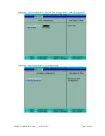
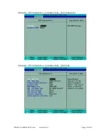
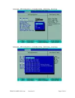
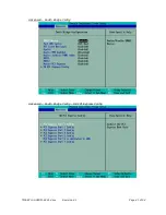
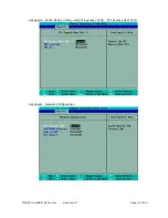
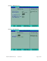
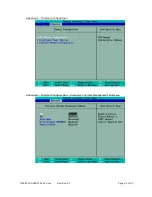
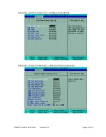
Страница 38: ...creens The BIOS setup utility allows setting of various board parameters The following pictures show the different setup menus The Hurricane QM57 specific settings are explained here Phoenix SecureCore BIOS Main Phoenix SecureCore BIOS Main System Information ...

Страница 39: ...TME EPIC HURQM R2V1 docx Revision 2 1 Page 33 of 52 Advanced Advanced Boot Configuration ...

Страница 40: ...TME EPIC HURQM R2V1 docx Revision 2 1 Page 34 of 52 Advanced ACPI Configuration Advanced Processor Configuration ...

Страница 41: ...TME EPIC HURQM R2V1 docx Revision 2 1 Page 35 of 52 Advanced Processor Configuration Processor Power Management Advanced Peripheral Configuration ...

Страница 42: ...TME EPIC HURQM R2V1 docx Revision 2 1 Page 36 of 52 Advanced HDD Configuration Advanced IMC Configuration ...

Страница 43: ...TME EPIC HURQM R2V1 docx Revision 2 1 Page 37 of 52 Advanced IMC Configuration NB Common Configuration Advanced IMC Configuration NB Common Configuration VT for Directed I O ...

Страница 44: ...TME EPIC HURQM R2V1 docx Revision 2 1 Page 38 of 52 Advanced IMC Configuration NB Common Configuration Video Configuration Advanced IMC Configuration Arrandale Config ...

Страница 45: ...TME EPIC HURQM R2V1 docx Revision 2 1 Page 39 of 52 Advanced IMC Configuration Arrandale Config PEG Configuration Advanced IMC Configuration Arrandale Config IGD Config ...

Страница 46: ...TME EPIC HURQM R2V1 docx Revision 2 1 Page 40 of 52 Advanced IMC Configuration Arrandale Config IGD Config Boot Type Advanced IMC Configuration Arrandale Config IGD Config Panel Type ...

Страница 47: ...TME EPIC HURQM R2V1 docx Revision 2 1 Page 41 of 52 Advanced South Bridge Config Advanced South Bridge Config SB PCI Express Config ...

Страница 48: ...TME EPIC HURQM R2V1 docx Revision 2 1 Page 42 of 52 Advanced South Bridge Config SB PCI Express Config PCI Express Root Port1 Advanced Network Configuration ...

Страница 49: ...TME EPIC HURQM R2V1 docx Revision 2 1 Page 43 of 52 Advanced SMBIOS Event Log Advanced ME Configuration ...

Страница 50: ...TME EPIC HURQM R2V1 docx Revision 2 1 Page 44 of 52 Advanced Thermal Configuration Advanced Thermal Configuration Processor Thermal Management Submenu ...

Страница 51: ...TME EPIC HURQM R2V1 docx Revision 2 1 Page 45 of 52 Advanced Thermal Configuration Intelligent Power Sharing Advanced Thermal Configuration Platform Thermal Configuration ...

Страница 52: ...TME EPIC HURQM R2V1 docx Revision 2 1 Page 46 of 52 Security Boot ...

Страница 53: ...t 4 2 Drivers Software drivers for Chipset Ethernet and graphics adapter are available for the Hurricane QM57 These drivers can be downloaded from LiPPERT s website http www lippertembedded com Follow the installation instructions that come with the drivers ...

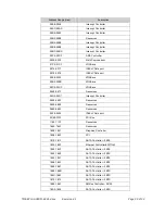
Страница 54: ...000000 EFFFFFFF Resources F0000000 F03FFFFF Graphics Controller F0400000 F041FFFF Ethernet Controller 82574L F0400000 F04FFFFF PCI Express 3B4A F0420000 F0423FFF Ethernet Controller 82574L F0700000 F071FFFF Ethernet Controller 82577LM F0720000 F0723FFF PCI Device F0724000 F072400F AMT F0726000 F0726FFF PCI F0727000 F0727FFF Ethernet Controller 82577LM F0728000 F07283FF USB Enhanced Host Controller...

Страница 55: ...roller 0000 0CF7 PCI Bus 0020 0021 Interrupt Controller 0024 0025 Interrupt Controller 0028 0029 Interrupt Controller 002C 002D Interrupt Controller 002E 002F Resources 0030 0031 Interrupt Controller 0034 0035 Interrupt Controller 0038 0039 Interrupt Controller 003C 003D Interrupt Controller 0040 0043 Timer Controller 004E 005F Resources 0050 0053 Timer Controller 0060 0060 Resources 0061 0061 Res...

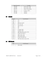
Страница 56: ...ASave 03C0 03DF VGASave 0400 047F Resources 04D0 04D1 Interrupt Controller 0500 050F Resources 0600 0603 Resources 0680 069F Resources 0A79 0A79 ISAPnP Data port 0D00 FFFF PCI Bus 1180 11FF Resources 164E 164F Resources 1800 1807 Graphics Controller 1808 180F PCI 1810 181F SATA Controller 3B2E 1820 183F Ethernet Controller 82577LM 1840 184F SATA Controller 3B2E 1850 1853 SATA Controller 3B2E 1854 ...

Страница 57: ...rupts IRQ Bus System Resource 0 ISA Timer 8 ISA Timer 9 ISA ACPI conform System 13 ISA Math coprocessor 7 PCI Graphic Controller 7 PCI AMT 12 PCI AMT 16 PCI PCI Express 3B42 16 PCI PCI Express 3B4A 16 PCI USB Enhanced Host Controller 3B3C 16 PCI Ethernet Controller 82574L 19 PCI SATA Controller 3B2D 19 PCI SATA Controller 3B2E 20 PCI Ethernet Controller 82577LM 23 PCI USB Enhanced Host Controller ...

Страница 58: ...RY a computer and other electrical devices Is your display ok Is the monitor powered on Is the monitor s video cable plugged into the video connector Double check the brightness and contrast settings Plug the monitor into another computer if possible to verify the monitor is not the problem Remove all additional devices from the system Only the processor board power supply monitors and the keyboar...

Страница 59: ...Phone 49 621 432140 Fax 49 621 4321430 E mail sales lippertembedded com support lippertembedded com Website www lippertembedded com US Office LiPPERT Embedded Computers Inc 2220 Northmont Parkway Suite 250 Duluth GA 30096 USA Phone 1 770 295 0031 Fax 1 678 417 6273 E mail ussales lippertembedded com support lippertembedded com Website www lippertembedded com ...

Страница 60: ...k to its manual Returning Products for Repair To return a product to LiPPERT for repair you need to get a Return Material Authorization RMA number first Please fill in the RMA Request Form at http www lippertembedded com service repairs html and send it to us We ll return it to you with the RMA number Deliveries without a valid RMA number are returned to sender at his own cost LiPPERT has a writte...

Страница 61: ...onnects computers peripherals and more at www usb org PCI Express PCI Express Specification Revision 1 1 at www pcisig com specifications pciexpress ACPI Advanced Configuration and Power Interface Specification ACPI Revision 3 0 at www acpi info spec htm SMB System Management Bus SMBus at www smbus org ...

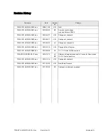
Страница 62: ...UW Changes at chapter 4 TME EPIC HURQM R0V4 doc 2010 06 24 JS Changes at chapter 3 5 TME EPIC HURQM R0V5 doc 2010 07 15 UW Changed Block Diagram TME EPIC HURQM R0V6 doc 2010 09 09 PK Ch 1 2 Correct article numbers TME EPIC HURQM R0V7 docx 2010 10 14 JS MF Reference Designators added to Connector Descriptions Ch 3 3 Text corrections TME EPIC HURQM R1V0 doc 2010 12 14 UW Changes at chapter 4 TME EPI...

Отзывы: