3
Wiring your Railroad Control Tower
T
he Railroad Control Tower operates best at 12 to 18 volts (AC). You may choose to wire this
accessory to the accessory terminals on your transformer, a separate accessory power sup-
ply, a Lionel Lockon (available separately, 6-62900), or a FasTrack terminal section (available
separately, 6-12016 ). You need the ends of the wires to be stripped back 1/4” to 3/8”.
To strip the wires, use a pair of wire strippers or a sharp knife. Only an adult
should perform this task! Always use care when stripping wires.
Wire this accessory to the spring clip terminals on the underside of the base. There are three
wiring options, depending on how you want to operate the accessory.
To make the spring clip terminal connections, press down on the top of the ter-
minal clip so that a metal loop is exposed. Slide the bare end of the wire into the
exposed loop. Release pressure on the terminal clip, allowing the crimped metal to
pinch the end of the wire in the metal loop. Gently tug on the wire to check if the
hold is secure.
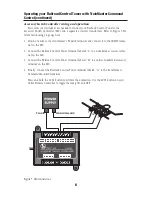
First, you may choose to leave the light on, controlling only the animation with the switch.
This is illustrated in Figure 1.
Caution!
A
U
POWER
SUPP
LY
COMMON/GROUND/U
POWER
SUPP
LY
POWER/A
OR
OR
POWER
SUPP
LY
2
1
U
A
A
U
Figure 1. Wiring for switch control of the animation
Note!


