


6. Ordering information
M C - 3 5 8 2 L – N C – 8 V R D A A 0 A 0 – d d – e e – f f
[1]
[2]
[3]
[4]
[5]
[6]
[7]
[1] Series model
MC: Mass Flow Controller Series
[2] Valve mode
NC: Normally close (No treatment))
[3] Fitting
8VRD: 12.7mmVCR (Width size171.4mm)
※ Please consult for more information.
[4] Optional
※ Default setting is labeled “AA0A0”. Please consult for more information.
[5] Gas type
[6] Full scale flow rate
[7] Flow rate unit
SLM (0 ºC standard)
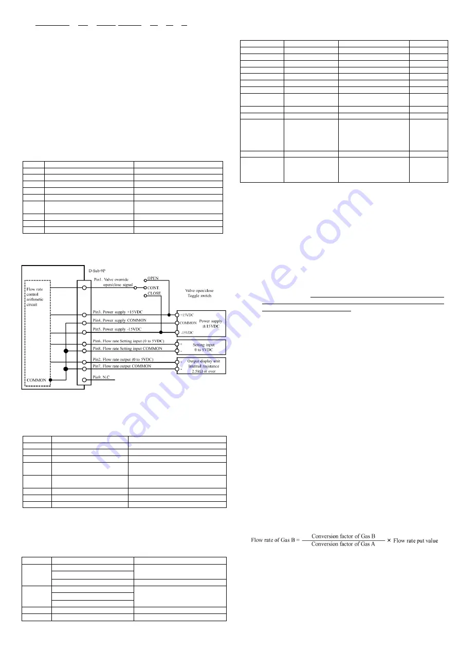
7. Connection
(1) Analog interface connector
Mounted connector : D-Sub 9 pin(male)
Pair connector : D-Sub 9 pin(female) (Fixed size of screw : M3)
Pin No.
Single name
Function
1
Valve on-off input (Note1)
+15VDC: OPEN,
-15VDC: CLOSE
2
Flow rate output signal 0 to 5VDC
Flow rate output voltage plus side 0 to 5VDC
3
Power supply input +15VDC±3%
Power supply (plus) 100mA
4
Power supply COMMON (Note2)
COMMON ±15VDC
5
Power supply input -15VDC±3%
Power supply (minus) 50mA
6
Flow rate setting signal 0 to 5VDC
(Note1)
Flow rate setting voltage plus side 0 to 5VDC
7
Flow rate output COMMON (Note2)
Flow rate output voltage COMMON
8
Flow rate setting COMMON (Note2)
Flow rate setting voltage COMMON
9
N.C.
N.C.
Note1) Input impedance of flow rate setting signal is 100kΩ. Valve override impedance is 100kΩ.
Note2) Pin No.4,7,8 are connected internally.
Wirings should be done as shown below in order to remove the effect of potential difference
among the COMMON.
Do not connect. Flow rate setting signal COMMON[8],Flow rate output signal COMMON[7],
and Power supply COMMON[4] in
the power supply unit.
(2) Digital interface connector
Mounted connector : RJ-45 Modular jack
Pair connector : RJ-45 Modular plug
Pin No.
Signal name
Function
1
Signal COMMON
RS-485 Signal COMMON
2
Signal COMMON
RS-485 Signal COMMON
3
N.C.
N.C.
4
Signal [- Txd / Rxd ]
RS-485 2-wire system transmitter.
receiver minus signal
5
Signal [+ Txd / Rxd ]
RS-485 2-wire system transmitter.
receiver plus signal
6
N.C.
N.C.
7
N.C.
N.C.
8
N.C.
N.C.
8. Alarm functions
This MFC features two alarm modes: alarm A and alarm B. Using a digital
interface, alarm output of the digital connector or LED indicator located on top of
the MFC housing can monitor the alarm status. As alarm settings can only be
changed using digital communication, please carry out necessary changes using
this method. For details, please refer to the Interface Instruction Manual.
Alarm
Set off
LED indicator
A
Setting value≠ flow rate output
Continuous Red
Flow totalizer Alarm level 2
Power supply voltage (+15VDC) drop
Off
B
Voltage of valve control change
Red (every 0.5sec flashing)
Abnormal zero offset (Note3)
Flow totalizer Alarm level 1
Other
Command error
Continuous Red (every 0.5sec flashing)
Normal
-
Green (every 1sec flashing)
9. Initial setting value (factory shipped value)
This MFC is provided with a software switch for operation mode setting. Before
operation, input the necessary data for various functions by using the digital
interface. Details of the functions are described in the special function manual.
Software switch
Available values
Function
Default
Device number
00 to 99
MFC No. Registration
00
Alarm A range
0 to 99 [%]
Setting Alarm A range
5%
Alarm B range
0 to 99 [%]
Setting of Alarm B range
20%
Alarm timer
0 to 99 [seconds]
Setting of Alarm timer
5 seconds
Alarm A output
Enable / Disable
Setting of Alarm A output
Enable
Alarm B output
Enable / Disable
Setting of Alarm B output
Disable(Note3)
Operation mode
Analog / Digital
Switching of Analog/digital
Analog
Power on mode
Analog / Preset
Switching of Operation mode
in power turning on
Analog
Valve control
C / O / H / S
Close / Open / Hold / Servo
Servo
Control speed
FAST / SLOW
Switching of Response speed FAST
Control mode
2%Close/2%Hold/ Normal
Control mode switching
(at flow rate setting <2%)
2%Close: Valve Close
2%Hold: 2% Control
Normal: Normal Control
Normal
Conversion factor
0.6666 to 1.500
Conversion factor setting
1.0000
Communication
protocol
9600 to 38400bps
8bit / 7bit
Odd/Even/ None
1bit / 2bit
Baud rate
Character length
Parity
Stop bit
9600bps
7bit
None
2bit
Note3) Zero adjustment error alarms regardless of the “Enable” / “Disable” of the alarm.
·If a zero set input of longer than 5seconds is input the Baud rate will be set to 9600bps and other
communication protocols will be returned to initial value (factory shipped value).
10. Operation
(1) Procedure
1)
This product is packed in a clean room before shipment. Please break the
seals in a clean room after taking it out of its box.
2)
Check the gas type and flow rate, and check the direction of the gas flow
and the MFC before installation.
3)
Check for gas leaks from the tubing with a helium (He) leak detector.
4)
Connect the interface connectors according to the Connector tale.
5)
Power requirements are +15VDC: 100mA and -15VDC: 50mA. Check the
voltage, polarity, and capacitance of the power supply voltage.
6)
Turn on power supply and let the equipment warm up for at least 5 minutes
(Recommended time: 30min).
7)
Adjust the zero point by pressing the zero adjustment, switch located on
the top of the MFC.
Before zero-point adjustment, check that gas is not
being supplied and the device was warmed up for 30 minutes or more
in order to ensure sensor stability.
8)
Input the flow rate setting signal and supply gas with required differential
pressure to the MFC. The MFC will begin to control the gas flow in
proportion to the preset voltage. Full-scale voltage is 5VDC. Maximum
input voltage is ±15.5VDC.
9)
When the output flow rate signal is used, the tolerance voltage of the
external device should be more than ±15.5VDC. When it’s connected the
output valve may be within the range of the maximum voltage ±15.5VDC.
10)
Complete shut off cannot be achieved with the mass flow controller. If
complete shut off is desired, a shut-off valve should be installed.
11)
When a highly reactive gas is used, thoroughly purge all foreign matter
from the tubing and the MFC before operation.
12)
When contaminated gas is used, install a filter at the equipment inlet.
13)
Use the MFC within the range of the operating temperature (5 to 50°C),
and keep it at the same temperature with the gas. If used in any
environment that does not meet the above-mentioned requirements, the
flow rate cannot be measured accurately and the device may fail.
14)
Do not switch the power supply on and off within one second. It may cause failure.
(2) Valve control signal
The MC features a forced valve open/close input function.
The connector pin No.1 is used to input the internal valve open/close signal.
By inputting this signal, a forced opening/closing of the internal valve can be
performed without depending on the value of the flow rate preset signal.
When +15VDC is input: fully open
When –15VDC is input: fully closed.
(3) Conversion factor
The MFC is preset based on the kind of gas and the flow rate. If a gas that is not
specified is supplied, the controlled flow rate may be different from the actual flow rate.
This difference is called a conversion factor, and is normally represented by a ratio
with N
2
. When gas B is fed into the MFC, which was calibrated with gas A, the
controlled flow rate is shown below.
The accuracy of this value may be decreased if the character of the gas is greatly
different. Also, the value of the MFC has been adjusted based on the viscosity and
density of the gas, therefore if a gas other than the calibration gas is applied, the
operating pressure range may be altered. The conversion factor can be set at any desired
value, with an operating range of 0.6666 to 1.5000. If the conversion factor value
exceeds this range, the operation of the MFC become unstable. The accuracy is different
from the standard specifications of the MFC, when the conversion factor is changed.
(4) Digital interface
The MFC features the RS-485 serial digital interfaces. Many special functions
can be employed using the digital interfaces. Please refer to other manuals
(Digital Interface Manual, Special Function Manual, Command Chart).


