


Hardwire Conversion Kit (2GIG-TAKE-KIT1) | Installation Instructions
Copyright © 2014 Linear LLC.
3
NOTE:
Terminals
3
‐
10
on
the
super
switch
correspond
to
zones
1
‐
8.
For
example,
wire
the
positive
(HI)
side
of
zone
1
on
the
Super
Switch
to
terminal
3.
3
Repeat
the
steps
above
for
each
additional
zone.
4
Group
the
LO/(GND)
wires
together
and
connect
them
to
terminal
1/G
(GND)
of
the
Super
Switch.
5
Replace
the
front
cover
on
the
Super
Switch.
6
Ensure
the
power
supply
is
mounted
in
the
enclosure
included
with
the
2GIG
‐
TAKE
‐
KIT1.
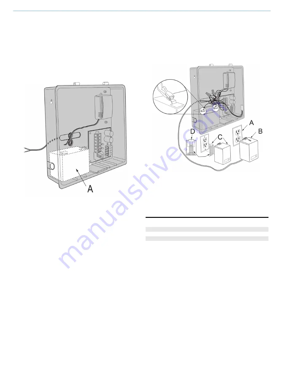
7
Position
the
backup
battery
in
the
recommended
location
in
the
enclosure.
Figure 5
Recommended Location for Backup Battery (Not Included)
8
Connect
the
Super
Switch
to
the
backup
battery
as
follows:
8a
Connect
the
RED
(BAT+)
wire
from
the
Super
Switch
to
the
RED
terminal
on
the
backup
battery.
8b
Connect
the
BLACK
(BAT
‐
)
wire
from
the
Super
Switch
to
the
BLACK
terminal
on
the
backup
battery.
9
Connect
the
Power
Supply
wires
to
the
backup
battery
as
follows:
9a
Connect
the
RED
(BAT
+)
and
BLACK
(BAT
‐
)
wires
(provided)
from
the
power
supply
to
the
BAT
+
and
BAT
‐
terminals
on
the
Power
Supply
Board.
9b
Connect
the
Spade
Lugs
to
the
Power
Supply
Ground
and
12
V
wires
to
the
corresponding
Quick
Disconnect
Connectors
on
the
Super
Switch
wires.
The
Super
Switch
should
already
be
connected
to
the
backup
battery.
9c
Connect
the
16.5V
AC
leads
for
the
transformer
to
the
16.5V
Power
Supply.
NOTE:
To
avoid
potential
damage
to
the
transformer
and
connected
devices,
measure
the
transformer’s
output
voltage
before
connecting
it
to
the
Power
Supply
Board.
IMPORTANT:
To
avoid
nuisance
low
battery
indicators
from
connected
zones,
always
power
up
the
battery
before
connecting
AC
power.
If
you
experience
an
issue,
see
10
Connect
the
16.5
V
AC
leads
to
the
AC
terminals
on
the
Power
Supply
Board.
11
Connect
the
plug
‐
in
transformer
(included)
into
an
unswitched
wall
outlet.
12
Prepare
to
secure
the
transformer
to
the
outlet
as
follows:
•
For
a
standard
wall
outlet,
screw
the
transformer
to
the
outlet.
The
screw
is
included
with
the
plug
‐
in
transformer.
OR
•
For
a
decora
wall
outlet,
affix
the
double
‐
sided
adhesive
tape
to
the
transformer.
Then
adhere
the
transformer
to
the
outlet.
Figure 6
Connecting Power to the Hardwire Conversion Kit
Recommended Maximum Current Draw
The
maximum
current
draw
from
external
devices
shall
not
exceed
the
recommendations
in
the
table
below:
Troubleshooting the Low Battery Alert
If
a
low
battery
alert
appears:
1
Unplug
the
transformer
to
power
down
the
Power
Supply.
2
Remove
all
connections
from
the
battery.
3
Test
the
battery’s
voltage
with
a
battery
life
test
meter
(not
multimeter).
4
If
the
battery
is
fine,
rewire
the
Super
Switch.
5
After
rewiring
the
Super
Switch,
reconnect
the
battery
connections,
connect
power
to
Terminal
2
on
the
Super
Switch,
and
then
plug
in
the
transformer.
NOTE:
To
clear
the
low
battery
alert,
you
may
need
to
open
and
close
all
of
the
zones
or
to
reboot
the
Control
Panel.
To
reboot
the
panel,
go
to
the
Installer
Toolbox
,
press
System
Configuration
,
and
the
press
End
at
the
question
screen.
When
the
Summary
of
System
Configuration
screen
appears,
ensure
the
Save
Changes
box
is
selected.
Then
press
Exit
.
NOTE:
All
of
the
ground
wires
must
be
grouped
together
and
connected
to
the
ground
port
of
the
Super
Switch.
A
Backup
Battery
A
Wall
Outlet
B
Plug
‐
in
Transformer
and
Screw
(included)
C
Plug
‐
in
Transformer
and
Double
‐
Sided
Adhesive
Tape
(included)
for
Decora
Outlets
D
Back
‐
side
of
Plug
‐
in
Transformer
with
Double
‐
Sided
Adhesive
tape
affixed
When
this
number
of
Super
Switch
Modules
are
installed:
Do
not
exceed
this
maximum:
Three
(3)
Modules
350
mA
Two
(2)
Modules
400
mA
One
(1)
Module
450
mA


