


3
dc1575bfa
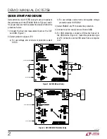
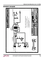
DEMO MANUAL DC1575B
OPERATION
The DC1575B is used to evaluate the LTC
®
4362 in two
protection configurations selected at JP2 for overvoltage
and overcurrent protection, or overvoltage, overcurrent,
and negative voltage protection. The device in need of
protection is connected to the OUT test point or to the
USB output connector J2. An input supply is connected
at V
IN
or a USB source is connected at J1.
ON
Control
The
ON
pin on the LTC4362 is controlled at JP1. Select
ENABLE to enable the LTC4362, or DISABLE to enter a
low current sleep mode.
Protection OV/OC
The first selection at JP2 is OV/OC protection which pro-
tects against overvoltage and overcurrent. The LTC4362
turns on an internal N-channel MOSFET when the input
voltage is below the overvoltage threshold. An internal
current sense resistor provides overcurrent detection.
In the case of an overcurrent, the LTC4362-2 used in the
DC1575B automatically tries to turn the internal MOSFET
back on. An orange input LED indicates if the input supply
is on while a green OUT LED indicates the gate is on and
input is connected to the output.
Protection OV/OC/NV
The second selection at JP2 is OV/OC/NV protection which
protects against overvoltage, overcurrent and negative
voltage. The LTC4362 turns on an internal N-channel
MOSFET when the input voltage is below the overvoltage
threshold. A P-channel MOSFET is driven by the GATEP pin
of the LTC4362 to protect the output against an inadvertent
negative voltage connection at the input. An internal current
sense resistor provides overcurrent detection. In the case
of an overcurrent, the LTC4362-2 used in the DC1575B
automatically retries to turn the internal MOSFET back
on. The orange V
IN
LED indicates if the input supply is on
while a green OUT LED indicates the gate is on and input
is passed over to the output. A red –V
IN
LED indicates if
a negative input voltage is present.
USB Protection
DC1575B also provides connection for USB protection.
First connect a USB device with a USB cable at J2. Select
the protection type at JP2 and match this with JP3. Select
ENABLE at JP1. The USB source can then be connected
at J1.


